Sheet metal fabrication complements WenXinDa stamping and die tooling projects with related brackets, covers, panels, and assemblies. Cutting, bending, joining, and hardware installation provide a flexible route for supporting parts or designs that do not yet justify dedicated stamping tooling. Send the finished drawing and quantities so the complete scope can be compared.
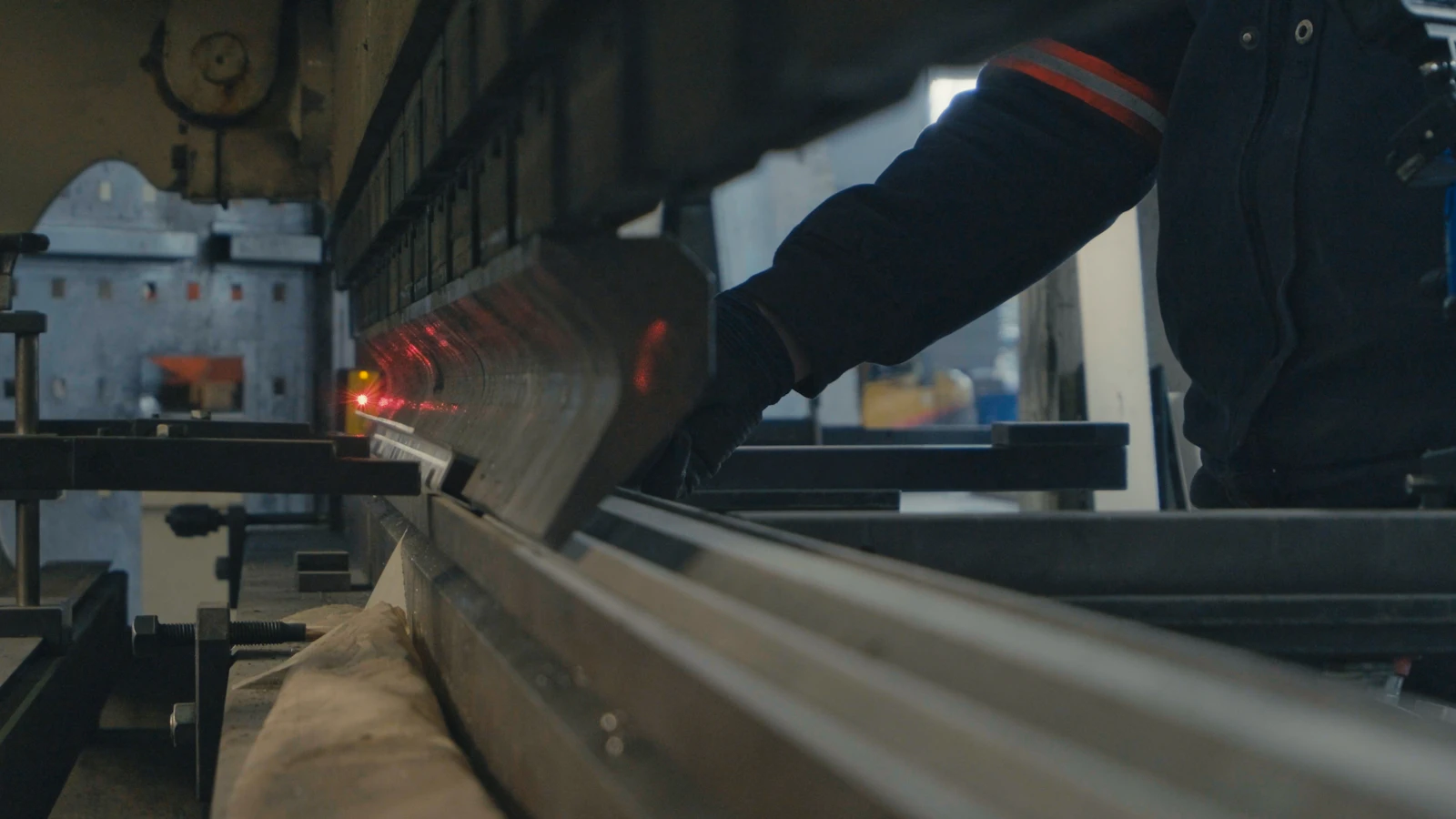
Cut the profile, form the flanges, then join and finish the component. Planning the sequence around mounting points and visible surfaces helps an enclosure or bracket fit correctly after every operation.
Start with the part function, then choose the operations that create its working features.
Sheet metal forming
Built to fit the assembly
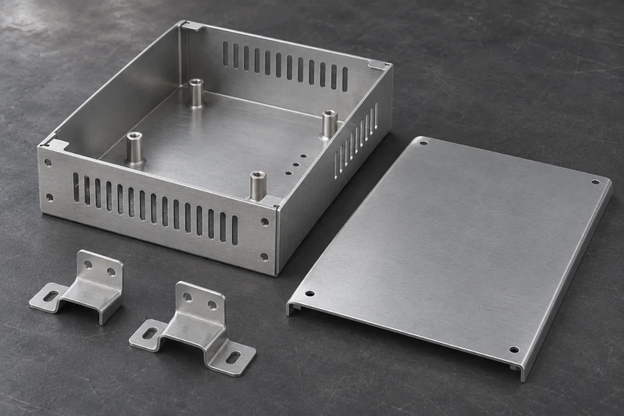
Mounting holes, folded flanges and mating panels are reviewed in the finished shape, where alignment matters.
Cut, form and join together
Plan the bend sequence, weld access and hardware positions before cutting the first blank.
Finish protected to delivery
Visible faces, threads and protruding hardware guide both the finishing plan and protective packing.
01 Scope
Practical manufacturing support for your parts
A good part brings together the right material, an efficient manufacturing route and a finish that suits its working environment. These are the details we connect during project review.
01
Assembly-level planning
Keep panels, fasteners and welded supports in one manufacturing plan. Assembly views help reveal interference before it reaches the fitting bench.
02
A route that fits your order
A flexible laser-and-bend route supports new designs and varied batches. Stable repeat demand can justify dedicated fixtures or tooling.
03
Finishing details
Powder coating, plating and exposed metal finishes each need their own surface preparation. Mark the visible side and the interfaces that must remain clear.
When to choose sheet metal fabrication
Sheet fabrication is a useful starting route for parts made from a consistent sheet thickness: covers, trays, guards, brackets, panels, and welded enclosures. It allows a flat blank to become a functional three-dimensional shape through cutting, bending, and assembly.
Part requirement
Why sheet metal can fit
What to compare
Lightweight protective cover
Formed flanges add stiffness to a relatively thin blank.
Access openings, panel removal, and finished cosmetic faces.
Mounting bracket
Cut profiles and bends can place attachment features without machining a full block.
Bend-to-hole dimensions, fastener access, and load direction.
Electrical enclosure
Panels, seams, hardware, and coatings can be planned as an assembly.
Clearance, grounding points, sealing, and the order of finishing and installation.
Thick precision interface
A fabricated blank may still reduce overall material removal.
Whether critical bores or faces need secondary CNC machining.
For a stable design with repeat demand, compare a stamping die and recurring part cost before fixing the route. Supporting CNC work can be reviewed for specific solid or mating features.
Typical sheet metal scope
A fabricated part is more than a cut profile. Connecting these operations gives you a finished component with the right shape, fastening points and surface condition.
Process
What we use it for
Notes
Laser cutting
Flat blanks, light gauge brackets
Nesting and edge quality per material
CNC press brake
Controlled bends, repeat setups
Bend radius, flange access and sequence matched to the formed geometry
Welding
Frames, cabinets, weldments
Specify joint type, weld symbols, and inspection requirements
Hardware insertion
Self-clinching fasteners and inserts where specified
Provide fastener reference and installation direction
For repeat assemblies, a fixture can help control the relationship between mating panels and fastening points.
Choose the sheet for both forming and service. Mild steel offers versatile fabrication options, stainless supports exposed or corrosion-sensitive parts, and aluminum reduces weight. Grade, temper and thickness also influence bend radius, springback and the finish that works best.
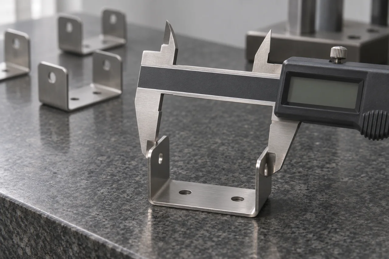
Checking a formed feature against the part specification
Select a sheet grade for forming and service
Material choice is more than a thickness value. A grade that bends cleanly may need a different finish for the working environment, while a prefinished sheet may limit welding or touch-up options.
Material family
Useful property to discuss
Design or finish question
Mild steel sheet
Formability and a broad range of fabrication routes.
What corrosion protection and weld appearance are needed?
Stainless steel sheet
Corrosion performance and cleanable exposed surfaces.
Which grade, surface finish, and grain direction should be maintained?
Aluminum sheet
Lower mass and a choice of decorative or protective finishes.
Which alloy and temper fit the bends, joining route, and finish?
Pre-coated sheet
A supplied surface condition can reduce later finishing steps.
Can cut edges, bends, welds, and hardware installation preserve the coating?
For a substituted grade or thickness, approve the change before flat patterns and tooling are released.
Flat patterns, bend allowance, and why the DXF matters
The flat pattern and finished-part drawing should describe the same revision. Bend allowance depends on material, thickness, radius, and tooling, so a supplied DXF may need review against the forming route. Include a STEP model where available and identify which finished dimensions control assembly fit. Agree any proposed flat-pattern changes before cutting.
Drawing detail
Why we ask
Bend direction and inside radius
Determines tooling and whether the part can be formed in one handling.
Weld symbols and finish after welding
Welding distorts; the finish sequence has to account for it.
Hardware callouts (PEM, rivet nuts)
Pilot hole size and insertion direction must match the fastener.
Cosmetic vs functional faces
Decides which side gets protected through cutting, bending, and packing.
A complete formed-part drawing helps keep bend, weld and hardware decisions aligned with the final assembly.
Edge finishing prepares cut and formed parts for handling, coating and assembly.Process detail
Bending details that affect fit and repeatability
Formed parts need two sets of thinking: the flat blank must be cut, and the finished shape must fit the assembly. Tie acceptance to the formed state and identify which flanges and holes are functional.
Feature
What can happen
What to clarify
Hole close to a bend
Forming can distort the hole or leave too little tool clearance.
Hole-to-bend distance, whether it is functional, and whether it can be made after bending.
Short return flange
The bend tool may not have enough material to grip or support.
Minimum flange function and whether a different bend sequence is acceptable.
Bend relief
Material can tear or bulge where a bend ends at a cut edge.
Relief shape, cosmetic side, and clearance to nearby features.
Multiple nearby bends
A formed flange can block the tool needed for the next bend.
Bend order, access for tooling, and which dimension controls the assembly.
Visible outer corner
The corner may show a gap or seam after forming and welding.
Required corner appearance, weld treatment, and coating coverage.
Use the finished shape as the acceptance reference; bend allowance translates that shape into a workable flat blank.
Joining and hardware: plan the assembly, not just each panel
Welds, rivets, and self-clinching hardware each change access and finishing. An assembly view helps show how components meet, which surfaces remain visible, and where a service technician needs access.
Assembly detail
Information to include
Why it affects the route
Welded seam
Weld symbols, side, appearance, and any post-weld dimensions.
Heat can move thin panels; finishing and any final machining must be sequenced.
Self-clinching fastener
Part number or standard, installation direction, and thread access.
Hole preparation and insertion must fit the sheet thickness and nearby bends.
Hinge, latch, or removable panel
Mating hardware and the intended opening direction.
Clearances need to work in the finished, coated assembly.
Electrical contact point
Grounding location, masking requirements, and contact hardware.
Coatings can interrupt conductivity if the contact area is not planned.
Specify whether hardware is supplied, installed, or packed separately in the quotation.
Define the visible finish and inspection state
A powder-coated cover and an unfinished mounting bracket need different acceptance criteria. Identify the outward-facing surfaces, edge condition, coating color and texture, masking, and handling marks that matter to the product.
For inspection, distinguish the flat blank from the final formed or welded assembly. Provide datum references and the critical dimensions in their final state; ask for a first-article or dimensional report when the project requires one. If the part must arrive free of scratches on a cosmetic face, describe the packaging and separation method in the RFQ as well as the finish.
What to send for a sheet metal quote
A useful package includes the formed STEP model, flat DXF if available, and a matching PDF drawing. Show material grade and thickness, bend radii and directions, weld and hardware callouts, finish, critical finished dimensions, and revision. Add the assembly view if panels must align with another component.
Include order quantity, expected repeat demand, destination, and any inspection or packing documents. If the flat pattern is only a reference, say so explicitly: the final blank can then be reviewed against the selected material and forming tools before material is cut. Approve any changes that affect fit, appearance, or revision control.
Follow the part through fabrication
Each operation can affect the next one. Reviewing the complete sequence helps avoid a finished panel that looks correct as a blank but no longer fits once it is bent, welded, coated, and fitted with hardware.
Stage
What is controlled
Buyer approval point
Cut blank
Profile, holes, orientation, edge condition, and material identity.
Confirm revision and any changes to the supplied DXF or nesting assumptions.
Form shape
Bend sequence, radii, flange dimensions, and springback.
Accept the finished-state dimensions that matter to the assembly.
Join and install hardware
Weld location, distortion, fastener direction, and access.
Confirm assembly fit, joint appearance, and supplied hardware list.
Finish and inspect
Coating coverage, masked interfaces, cosmetic faces, and final geometry.
Agree inspection report, appearance criteria, and protective packing.
Quote the complete sequence to keep cut blanks, formed parts and finished assemblies on the same comparison basis.
Compare the full fabrication quote
A cut-only quote is different from a delivered enclosure. Ask whether material purchase, forming, welding, fasteners, coating, final inspection, protective film, and packing are included. Confirm if a first-article review or fixture cost is separate from the unit price.
For a part that will be ordered repeatedly, also provide the release pattern and expected design changes. It may be economical to keep a flexible laser-and-bend route while the product evolves, then compare dedicated tooling if the form stabilizes and volume grows. Keeping the same finished-part specification across both routes makes that comparison useful.
Specify the component your assembly team needs to receive
A DXF defines a profile; an OEM build needs a component that fits. Connect the flat geometry to the formed envelope, mounting interfaces, installed hardware and final finish. This is especially useful for covers, brackets and enclosures whose acceptance depends on the relationship between several operations. Send the assembly view with the part drawing so the review addresses cutting, bending, joining and delivery as one scope.
Fabrication project brief
Manufacturing review
Approval that moves the build forward
Bent mounting bracket with a functional offset
Identify the mounting datums, installed offset and hole relationship. Review material condition, bend radius and forming access with the complete model.
A formed sample checked against the assembly datums and accepted in the specified finish condition.
Enclosure with a fitted cover and captive hardware
Review panel interfaces, corner joints, hardware direction, service access and visible faces. Connect the finish sequence to threads and electrical contact areas.
Fit of the complete enclosure, correct hardware and an agreed appearance reference for visible surfaces.
Machine guard or panel kit
Provide the bill of materials, part numbers and matching revisions. Define edge preparation, fastening interfaces and which pieces ship fitted or separately.
A clearly identified kit with the agreed part count, interface checks and packing for the receiving build.
Compare the complete fabricated part
A useful quote includes the operations required to reach the delivered condition: material, cutting, deburring, forming, joining, hardware, finish, inspection and packing. List any assembly trial or report your team needs before release. This makes it easier to compare suppliers against the same finished component and to decide whether a flexible fabrication route or dedicated tooling better fits future releases.
Bring us the current drawing, formed model and a short note about the installation or finish issue you want the next batch to address. Add release quantity, expected repeats and destination. For a multi-piece assembly, include the bill of materials and identify the parts that must arrive ready to install. Those details turn a general enquiry into a focused manufacturing review.
Replacing an existing enclosure or bracket? Share the fit issues, installation constraints and finish expectations with the drawing so the next batch addresses them.
Application brief
Use the application, mating features and approval checks to turn a drawing into a clear manufacturing brief. Bring your part number and the assembly requirement that drives the design.
Enclosure fit, fastening and formed mounting features
Equipment housings / supporting sheet metal
Equipment Enclosure Assembly
An equipment enclosure brings cut profiles, bends, hardware and surface finish into one assembly. A panel may pass its individual checks while access holes, mounting points or doors fail to line up after finishing. The project review follows the complete assembly and the receiving requirements, rather than quoting disconnected flat parts.
Engineering & inspection +
The objective is an enclosure package that is straightforward to receive and build into the equipment. Send the assembly model as well as individual drawings to make the fabrication scope easier to evaluate.
Engineering approach
Review the assembled model, panel drawings and mating clearances. Identify the visible faces, access needs and mounting features that control usability.
Plan bend order, tool access, weld locations and hardware installation together. Clarify which features require checking after forming or assembly.
Coordinate masking, coating thickness, labels and protective packing. List supplied hardware and separately supplied components in the purchase scope.
Approval checkpoints
Check the assembly datums, mounting pattern and agreed clearances.
Approve hardware position, thread access and specified joining details.
Inspect visible surfaces and protect finished parts for shipment.
Enclosures, guards, and brackets with defined mounting and access requirements.
Energy & electrical
Panels, bus bar supports, and frames where conductivity and clearance matter.
Mobility & hardware
Programs where repeatability and documentation matter as much as unit cost.
General OEM
Custom covers, access panels and formed assemblies that arrive ready for the next installation step.
03 Finishing
Finishing & post-processing
Finishing protects the part and prepares it for use. Choose the treatment around corrosion, wear, appearance and contact surfaces, with masking and final dimensions planned from the start.
Option
What it does
Common use
Powder coat
Durable color; mask critical surfaces as specified.
Covers, visible brackets
Passivate
Treatment specified for suitable stainless steel grades.
Stainless parts with defined corrosion requirements
Zinc plating
Sacrificial protection on steel.
Indoor hardware
Anodize (aluminum)
Decorative or protective oxide layer.
Panels and cosmetic faces
Explore the process
Explore the operation your part needs
See how each operation handles the geometry, material and assembly features in your design.
Sheet metal laser cutting
Flat blank geometry, edge condition, and cut features.
Start with the files you have and highlight the features that matter most. These four details help us connect your design to the manufacturing route and finished-part price.
01
Current revision
Provide the dimensioned drawing and available CAD with matching part number, revision, and units.
02
Material & finish
State the complete material specification, condition, finish requirements, and any permitted alternatives.
03
Critical features
Identify functional dimensions, datum features, cosmetic criteria, and required inspection records.
04
Quantity & delivery
Include release quantity, expected repeat demand, destination, and the required delivery date.
Include the destination, preferred Incoterm and named place. For large panels or finished enclosures, add pallet or crate needs and any restrictions on stacking, so packing protects the geometry and visible surfaces.
Is there a standard minimum order?
Send the quantity you need for the first build and the expected repeat quantity. Material purchase, forming setups and finishing batches affect the economical order size; quoting both stages helps you compare the practical options.
What files help?
DXF/DWG for flats; STEP for formed parts; PDF with welds, finishes, and critical dimensions.
Do you need both a flat pattern and a formed model?
The formed model shows how the part should fit; a flat pattern helps cutting review. Send both when available, with the same revision and a PDF showing the dimensions that matter in the finished state. The flat can be adjusted after the forming route is reviewed.
Can holes be placed close to a bend?
Sometimes, but the hole may deform during bending or interfere with tooling. Identify whether its final size and position are functional, and the layout can be reviewed for relief, sequencing, or a post-bend operation.
When should I specify a weld rather than a fastener?
Choose based on structural, service, appearance, and access needs. A weld creates a permanent joint and can distort thin material; a fastener may support repair but needs suitable installation access. Show the assembly function so the joint can be reviewed.
How do I define a cosmetic surface?
Mark visible faces on the drawing and state the finish, color or texture, acceptable marks, masking, and packaging protection. An appearance sample or written acceptance criteria can help align inspection before the first batch.
Can a formed panel include machined features?
Yes. A formed or welded blank may need a machined bore, thread, or locating face. Show which finished features control assembly and whether machining should happen after forming or welding. This lets the combined datum and inspection route be reviewed.
What should I check before changing sheet thickness?
Thickness affects bend allowance, flange fit, fastener selection, weight, and sometimes the finish. Update the model, flat pattern, and drawing together, then confirm whether the forming route and assembly clearances still work.
Next step
Let us help you move the part forward
Send your drawing with the material, quantity and target delivery date. Tell us where the part fits and what matters most, whether that is assembly, appearance, cost or repeat supply.