

Skip to content

Sheet metal / forming

Sheet Metal Bending & Formed Parts

Sheet metal bending turns a flat blank into a bracket, cover or enclosure with the stiffness and mounting surfaces needed for assembly. WenXinDa plans the material, bend sequence and finished dimensions together, helping OEM buyers get formed parts that align with their mating components. The review focuses on practical details: flange access, hole position, springback and the visible finish.

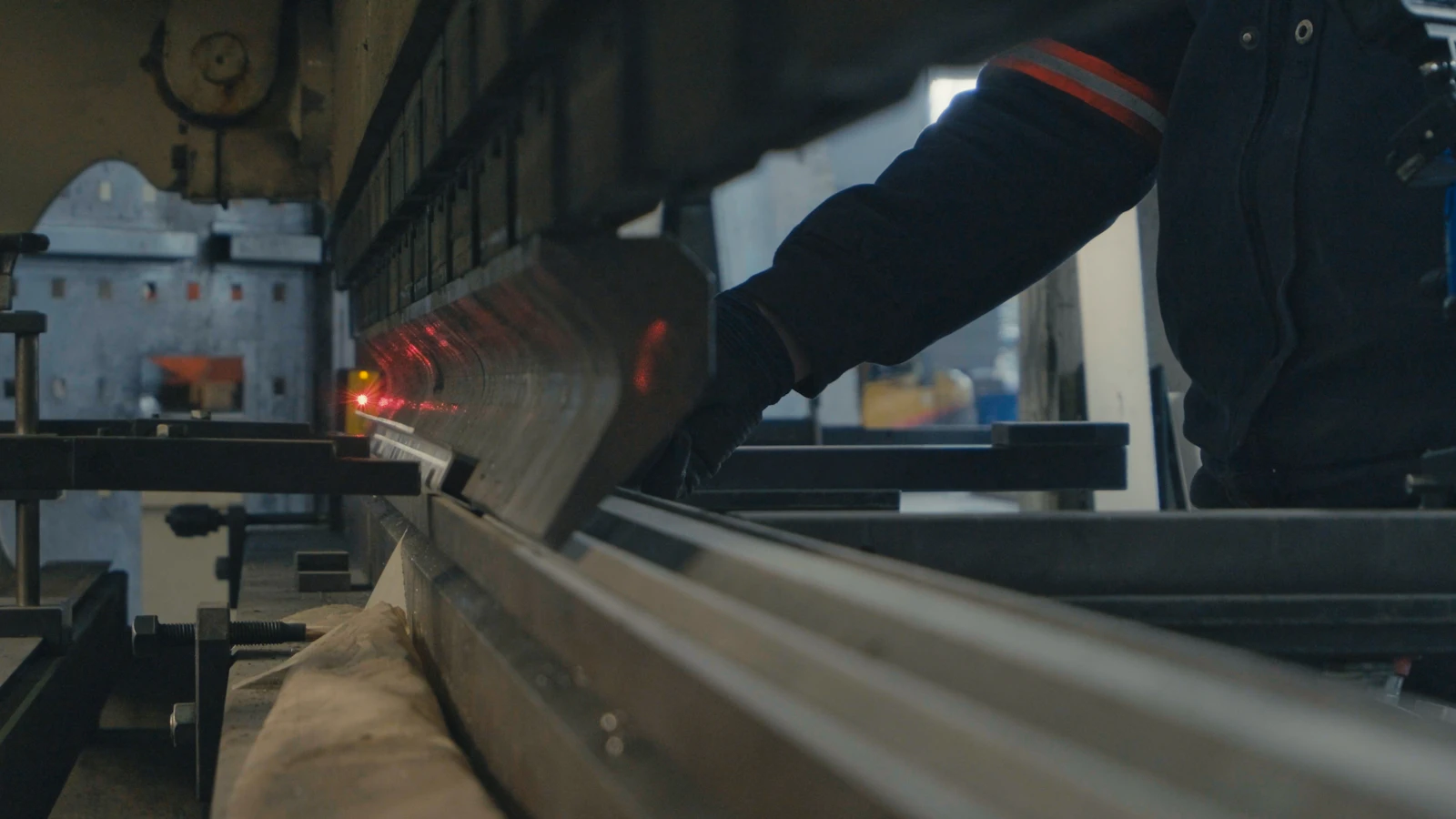
Operator forming a metal sheet on a press brake
Sheet metal bending on a press brake

Process at a glance

A bend changes more than the silhouette

Forming changes the relationship between holes, flanges and mating faces. Bend radius, material direction and springback affect the result. A good drawing defines the finished part and identifies dimensions that must be measured after bending.

The operation creates the geometry; the part function determines which features need the closest control.

Sheet metal forming A flat blank is cut and then bent into a part with flanges. The drawing defines bend direction and inside radius. FLAT BLANKFORMED PART02 / BEND
Sheet metal forming

01 Fit

When formed sheet metal is the right route

Bends add stiffness and useful geometry without the weight of a solid machined part. Formed sheet is a practical choice for equipment brackets, protective covers and enclosure panels.

Brackets

Flanges and formed ribs can provide stiffness while maintaining a light part. Hole positions near bends need special review.

Enclosures

Multiple walls, seams and mounting features can be formed from a flat pattern, then joined or fitted with hardware.

Panels and covers

Folded returns create safer edges and improved rigidity; visible faces need finish and handling requirements.

Design review

Plan bend sequence early

The bending sequence matters as much as the finished model. An early flange can block a later bend, and a hole close to the bend zone can distort. We look at those relationships before the blank is cut.

  • Identify whether the critical dimension is a bend angle, flange position or the complete installed envelope.
  • Show access for fastener insertion, assembly tools and neighboring components on return flanges or closed profiles.
  • Specify material grade, thickness and condition; bending behavior varies by material.
  • Identify inside radius and the finished angle where they matter.
  • Keep holes, slots and hardware locations clear of bend deformation zones where practical.
  • Use bend reliefs and corner treatments to reduce tearing or interference.
  • Mark which dimensions apply after bending and which faces serve as inspection datums.
Grinding the edge of a metal component
Edges and formed corners often need finishing reviewProcess detail

02 Decisions

Bending decisions to resolve before quotation

Use the finished geometry to define the part. The material and tooling then determine the flat pattern and sequence needed to produce it.

DecisionWhat to specifyWhy it matters
Finished envelopeInstalled height, width, diagonal relationships and datum referencesChecking only individual bend angles may not establish whether the complete formed part fits its assembly.
Hardware accessCaptive fastener location, installation direction and required tool clearanceThe bend sequence must leave a practical route for installing and using the specified hardware.
Material conditionAlloy, temper, thickness and grain orientationThese influence bendability and springback.
Bend geometryRadius, angle, flange length and sequenceTooling access and collision risk affect feasibility.
Critical interfacesHole-to-bend and face-to-face dimensionsThese define what to inspect on the finished part.
Finish and handlingCoating, cosmetic side and edge conditionPost-process handling can change appearance and fit.

03 Project route

A formed-part workflow

Work backward from the installed part: define the mating dimensions, plan the bends, then check the first formed piece against those interfaces.

  1. 01

    Define the finished part

    Share a formed 3D model, drawing and intended material.

  2. 02

    Review the blank

    Compare flat pattern, bend allowances, reliefs and tool access.

  3. 03

    Check the first part

    Verify angles, mating dimensions and any cosmetic face.

  4. 04

    Release and protect

    Agree finishing, stacking and protection of formed edges in transit.

04 Applications

Bent metal parts with useful strength and access

A flange may stiffen a panel, create a mounting face or protect an exposed edge. Its role tells us which dimension and finish deserve the closest attention.

Cover with mating flanges

Project brief: a cover needs to sit on an existing frame while leaving room for screws and service access. Identify the installed envelope, locating faces and cosmetic side. Review bend sequence, return flanges and tool access with the formed model. The acceptance check should address the final hole locations and the seating condition after coating, so the drawing describes the cover as it will be installed.

Bracket with a functional offset

Project brief: a bracket locates a sensor or electrical component away from a mounting face. The offset, flange angle and hole relationship work together. Dimension from the assembly datums and identify which direction allows adjustment. The forming review can then focus on material condition, bend radius and sequence. A first-part check against the complete formed shape gives the next release a useful reference.

Tray or channel with attached hardware

Project brief: a formed part includes return edges, captive fasteners and a protective finish. Review how the bends affect hardware insertion and fastening access before releasing the flat blank. Define the installed fastener specification and surfaces to keep clear during coating. The complete route can then connect cutting, bending, hardware installation and inspection around the ready-to-assemble component.

For an enclosure or multi-piece bracket, send the assembly view too. It shows whether the bend must leave room for a fastener, hinge, connector or neighboring panel.

Application project brief

See the part.
Plan the details that matter.

Use the application, mating features and approval checks to turn a drawing into a clear manufacturing brief. Bring your part number and the assembly requirement that drives the design.

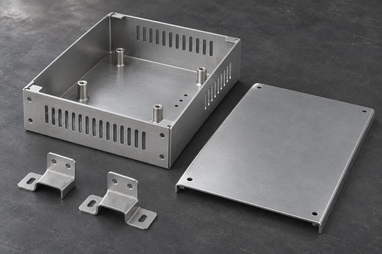
Folded metal enclosure with a removable lid and mounting brackets
Enclosure fit, fastening and formed mounting features

Equipment housings / supporting sheet metal

Bring the enclosure together.

An equipment enclosure brings cut profiles, bends, hardware and surface finish into one assembly. A panel may pass its individual checks while access holes, mounting points or doors fail to line up after finishing. The project review follows the complete assembly and the receiving requirements, rather than quoting disconnected flat parts.

The objective is an enclosure package that is straightforward to receive and build into the equipment. Send the assembly model as well as individual drawings to make the fabrication scope easier to evaluate.

Explore the project approach

Engineering approach

  • Review the assembled model, panel drawings and mating clearances. Identify the visible faces, access needs and mounting features that control usability.
  • Plan bend order, tool access, weld locations and hardware installation together. Clarify which features require checking after forming or assembly.
  • Coordinate masking, coating thickness, labels and protective packing. List supplied hardware and separately supplied components in the purchase scope.

Approval checkpoints

  • Check the assembly datums, mounting pattern and agreed clearances.
  • Approve hardware position, thread access and specified joining details.
  • Inspect visible surfaces and protect finished parts for shipment.

05 Common questions

Questions before you request a quote

Straightforward answers to the design, manufacturing and purchasing questions that come up before an order.

Why does a formed model matter when I already have a DXF?

The formed model shows the intended shape, bend relationships and access around nearby features. A flat profile alone does not establish the finished flange position or assembly envelope. Send both with a controlled drawing so cutting and bending follow the same requirement.

How should I specify a bracket that locates another component?

Identify the mounting datum, the locating interface and the dimensions that connect them in the formed condition. Include the mating component or installation sketch. This helps distinguish the functional offset and hole pattern from dimensions that can follow an agreed general tolerance.

Is the flat pattern or formed model more important?

The formed model and drawing define the part you want to receive. A flat pattern helps cutting preparation, but it needs to match the actual material, bend radius and tooling route. Send both when available.

Why can a hole distort near a bend?

The material around the bend stretches and deforms during forming. A nearby hole can change shape or position. Moving it, adding relief or producing it after bending can be options for a critical feature.

What is springback in sheet metal bending?

Springback is the elastic recovery that occurs after the bending force is removed. Material grade, temper, thickness and bend geometry influence it. The forming setup compensates for that behavior to reach the finished angle.

How can I make a bent part easier to manufacture?

Use consistent bend radii where practical, leave access for tooling and keep critical holes clear of bend deformation. Identify the final mating dimensions so the review can simplify other features without affecting fit.

Prepare an RFQ

Get a quote for your bent sheet metal part

Send the finished model and drawing, with the material and thickness. Add a flat pattern if available and highlight the dimensions that control assembly.

  • • Formed 3D model and dimensioned drawing
  • • Flat pattern if available, material and thickness
  • • Critical angles, flange lengths and hole positions
  • • Finish, hardware, quantity and inspection needs
Request a quote

Explore related manufacturing routes