
Skip to content

Sheet metal / cutting

Sheet Metal Laser Cutting for Custom Parts

Laser cutting creates custom metal profiles, mounting holes, slots and ventilation patterns directly from digital design files. WenXinDa supports laser-cut plates and blanks for OEM brackets, panels and enclosures, including the bending, hardware and finishing steps that follow. It is a flexible route for prototypes, varied part families and designs that are still evolving.

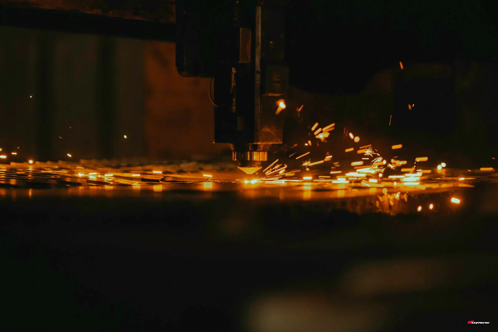
Laser cutting head cutting a metal sheet with visible sparks
Laser cutting begins with a controlled flat profile

Process at a glance

The flat pattern controls what comes next

A cut profile may be a final part or the starting blank for bending, hardware insertion and finishing. Hole-to-edge clearance, kerf, cut sequence and protective film can affect later work. When forming follows, the flat pattern and bend model need to agree.

The operation creates the geometry; the part function determines which features need the closest control.

Sheet metal forming A flat blank is cut and then bent into a part with flanges. The drawing defines bend direction and inside radius. FLAT BLANKFORMED PART02 / BEND
Sheet metal forming

01 Fit

Where laser cutting fits

Laser cutting is useful when the profile changes, several part numbers share a sheet grade or a dedicated blanking die would add unnecessary investment.

Flat brackets and plates

Contours, slots and mounting holes can be cut from sheet. Edge condition should be defined if the part is handled or assembled directly.

Blanks for formed parts

Cutting creates the flat pattern before bends. Bend reliefs and hole positions must account for the forming sequence.

Variable designs

Digital profiles are useful while a design changes or when multiple related shapes share material. Stable demand may justify comparing stamping.

Design review

Review the cut edge as an interface

A good cut profile has to work beyond the laser bed. Consider how the edge will be handled, where the part will bend and which holes locate the assembly.

  • For a bent component, provide the formed model and drawing together with the flat profile rather than asking the flat file to define the assembly.
  • List individual part numbers, thicknesses and quantities when several similar profiles belong to one build kit.
  • State material grade, sheet thickness and required surface condition.
  • Mark edges that contact a user or mate with another part, and specify deburring where needed.
  • Check small holes, narrow webs and sharp internal corners against the selected thickness.
  • Provide a flat pattern and formed model together when the part will be bent.
  • Identify grain direction, cosmetic side and protective film requirements when relevant.
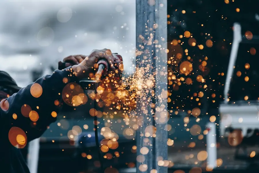
Grinding the edge of a metal component
Cut edges and downstream finishing need their own requirementsProcess detail

02 Decisions

Decisions behind a clean cut profile

Cut quality starts with the sheet and feature size. The complete part price also includes edge treatment, forming and the finish needed for installation.

DecisionWhat to specifyWhy it matters
Downstream routeBending, hardware, welding or coating required after cuttingThe blank should support the finished component, including feature access and the condition of edges used in later operations.
Part identificationPart numbers, orientation marks, kit contents and lot separationA group of similar profiles is easier to receive and assemble when identification is planned with the manufacturing scope.
MaterialGrade, temper, sheet thickness and finish sideThese influence cut quality, available stock and downstream forming.
Feature scaleSmall holes, slots and thin bridgesVery fine geometry may require design review or secondary operations.
Edge qualityBurr, discoloration and visible-edge expectationsThe cut state and any deburring must match the final use.
Next operationBends, hardware, welding and coatingThe blank should be optimized for the complete route, not cutting in isolation.

03 Project route

From profile file to accepted blank

Keep the flat profile tied to its revision and final use. That connects cutting, edge finishing and any downstream forming to the same part definition.

  1. 01

    Share the files

    Send the flat profile, 3D formed model if applicable, drawing revision and material specification.

  2. 02

    Review the profile

    Resolve small features, cut edges, grain direction and bend reliefs.

  3. 03

    Approve the sample

    Check critical hole locations, edge condition and fit in downstream assembly.

  4. 04

    Release the order

    Agree labeling, protection and separation of parts during shipment.

04 Applications

Laser-cut parts and blanks for OEM fabrication

From a simple mounting plate to a ventilated enclosure panel, the value is in producing the required profile without committing to a dedicated cutting die.

Flat mounting panel

Project brief: a panel has a mounting pattern, connector openings and a visible face. Identify the locating holes, edge quality and appearance side before quoting the cut profile. Review coating and hardware requirements with the panel drawing. If the component is delivered flat, define the condition accepted at receipt; if it is formed later, connect the blank to the finished-part drawing so the cut features support the next operation.

Blank for a formed bracket

Project brief: a laser-cut profile will become a bracket with multiple bends. Provide the formed model as well as any flat file. Review holes near bends, relief geometry, grain direction and the surfaces that control assembly. The complete route should connect cutting to deburring and bending rather than treating the DXF outline as the whole requirement. Quote the finished condition your assembly team needs.

Mixed parts for a machine build

Project brief: a build uses several plate profiles in different thicknesses or finishes. Supply an itemized part list with drawing revisions and quantities for each profile. Separate cosmetic and functional edge requirements, and state whether identification or kitting is needed. The sourcing package can then cover material selection, cutting, follow-on operations and packing around the actual set of parts required for the build.

Ordering a finished bracket or enclosure? Include bends, hardware, joining and coating with the cut profile so the quote covers the component you need at the assembly bench.

Application project brief

See the part.
Plan the details that matter.

Use the application, mating features and approval checks to turn a drawing into a clear manufacturing brief. Bring your part number and the assembly requirement that drives the design.

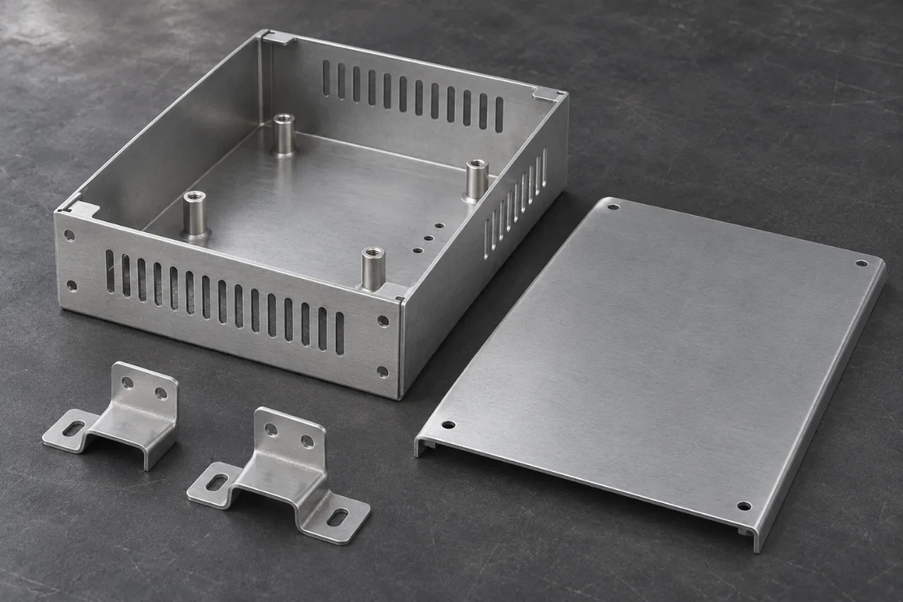
Folded metal enclosure with a removable lid and mounting brackets
Enclosure fit, fastening and formed mounting features

Equipment housings / supporting sheet metal

Bring the enclosure together.

An equipment enclosure brings cut profiles, bends, hardware and surface finish into one assembly. A panel may pass its individual checks while access holes, mounting points or doors fail to line up after finishing. The project review follows the complete assembly and the receiving requirements, rather than quoting disconnected flat parts.

The objective is an enclosure package that is straightforward to receive and build into the equipment. Send the assembly model as well as individual drawings to make the fabrication scope easier to evaluate.

Explore the project approach

Engineering approach

  • Review the assembled model, panel drawings and mating clearances. Identify the visible faces, access needs and mounting features that control usability.
  • Plan bend order, tool access, weld locations and hardware installation together. Clarify which features require checking after forming or assembly.
  • Coordinate masking, coating thickness, labels and protective packing. List supplied hardware and separately supplied components in the purchase scope.

Approval checkpoints

  • Check the assembly datums, mounting pattern and agreed clearances.
  • Approve hardware position, thread access and specified joining details.
  • Inspect visible surfaces and protect finished parts for shipment.

05 Common questions

Questions before you request a quote

Straightforward answers to the design, manufacturing and purchasing questions that come up before an order.

Should I send a flat pattern or the formed part model?

For a formed component, send the formed model and dimensioned drawing as well as the flat file if available. The finished geometry defines the requirement, while the flat pattern supports cutting and bending review. Identify which file is the released design authority for the order.

Can my quote include deburring, bending and hardware?

Yes. List the complete delivered scope and send the relevant drawing notes, hardware references and finish specification. Cutting, edge preparation and the follow-on operations can then be reviewed together. This lets purchasing compare finished components using the same acceptance basis.

What files are needed for laser cutting?

Send a DXF or DWG profile with units, plus a PDF showing material, thickness, revision and critical dimensions. For a formed part, add the 3D model so the flat and bends can be considered together.

Can laser-cut blanks be bent or welded afterward?

Yes. The flat pattern should include the reliefs, hole positions and edge details needed by the later operations. Show the finished part so cutting can be planned around the full fabrication route.

Should laser-cut parts be deburred?

Deburring is useful for handled edges, mating surfaces and parts moving into coating or assembly. Mark those edges and any cosmetic requirements so the cut and finished condition are clear.

When is stamping worth comparing with laser cutting?

Compare stamping when the geometry is stable and repeat demand can spread the die investment over enough parts. Include material yield, forming, finishing and revision costs in the comparison.

Prepare an RFQ

Send your profile for a laser-cutting quote

A DXF or DWG gives us the profile; the drawing adds the material, thickness and edge requirements that turn it into a usable part.

  • • Flat profile with units and drawing revision
  • • Material grade, thickness and quantity
  • • Edge, appearance and deburring requirements
  • • Bends, hardware, coating and inspection needs
Request a quote

Explore related manufacturing routes