Equipment housings / supporting sheet metal assembly
Sheet Metal Equipment Enclosure Assembly
An enclosure is purchased as an assembly problem, even when its quotation begins with separate flat parts. This project connects cut profiles, bend sequences, joints, installed hardware, coating, and final fit. It gives equipment buyers a way to define the finished housing and its approval requirements. Keep the assembly model, panel revisions, treatment, hardware, and inspection references connected. Ask the review to resolve the cover or mounting interface that matters most, then organize the quotation around a complete delivered housing.
- Customer
- Industrial equipment and housing OEM
- Component
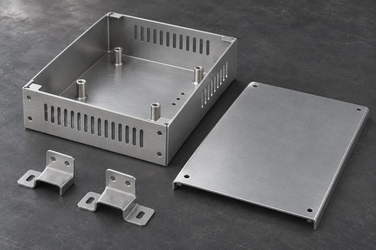
- Sheet metal housing with cover and installed hardware
- Manufacturing route
- Sheet cutting, bending, joining, hardware installation, coating, and final assembly
- Material
- Drawing-defined steel, stainless steel, or aluminum sheet
01 / The challenge
Make the requirement work in the real assembly.
The project involves a sheet metal equipment housing with a body, removable cover, internal mounting features, and installed hardware. The enclosure must fit the equipment it surrounds and allow the intended assembly and service operations. Send the complete model and bill of materials with the individual panel drawings. Show which components are supplied together and which are fitted by the receiving team.
Identify the external mounting points, internal component interfaces, access openings, cover engagement, and fastening arrangement. Define the assembly datums rather than treating every flat profile as a separate purchasing item. This makes the fabrication review useful for the finished equipment and helps the quotation include the operations that connect the panels into the required housing.
- Application
- An equipment housing combines a formed body, removable cover, internal mounts, and drawing-defined hardware.
- Main requirement
- Coordinate panel geometry, joints, installed hardware, access, and coating around the final equipment and cover interfaces.
- Supply scope
- A defined panel set or complete housing, including specified assembly work, hardware, finishing, inspection, and packing.
- Approval reference
- A released assembly model and bill of materials with panel revisions, material, finish reference, and final assembly checks.
02 / Engineering approach
Turn the difficult details into a manufacturing plan.
Keep flat files and formed drawings connected
Use the formed component drawing to describe the delivered part, including inside radii, bend direction, flange relationships, and critical mounting features. The flat profile supports cutting and blank preparation, while the formed model gives the assembly context. Keep part numbers and revisions aligned across the files. Mark any customer-controlled flat pattern and identify where the manufacturing layout is open for review.
Review cutouts and holes near bends with the formed geometry. Establish which openings must align with installed equipment and which can follow a practical clearance requirement. Add the fastener and joining details that appear after forming. The objective is a drawing package in which the cutting plan, bend sequence, and final assembly all refer to the same product definition.
Plan bend order around access and alignment
A panel's finished shape depends on how each bend can be made and located. Review bend order, tooling access, return flanges, narrow features, and the surfaces used to position the part. Keep the mounting pattern and cover relationship visible while the sequence is developed. A final measurement should describe the formed panel from the datums used in the assembly.
Where the design allows alternatives, compare them against the complete enclosure. A changed flange or joint may simplify forming while also changing hardware access or appearance. Show the proposed difference clearly, obtain the drawing decision, and connect the selected geometry to the sample plan. The buying decision stays focused on the finished housing rather than a single cutting or bending operation.
Make hardware a controlled part of the delivery
Specify each installed fastener, nut, standoff, insert, and bracket in the bill of materials. Provide the required thread, location, orientation, and installation side. Confirm whether hardware is supplied installed, supplied loose, or provided by the buyer. Include any functional requirement and check method for the installed hardware in the enquiry so it is part of the manufacturing and approval scope.
Review insertion access and the sequence relative to joining and coating. Identify the threads or contact areas that must remain available after finishing. Use the equipment assembly view to check driver access and engagement. A complete hardware specification turns a collection of pierced panels into a housing with the interfaces the equipment builder expects to use.
Connect joints, finish, and appearance
Show the required joints and their locations, the joining method, and any final cleanup standard. Distinguish visible external faces from internal surfaces and hidden joints. If welds or joining features affect the mounting relationship, include them in the assembly inspection plan. Coordinate the order of forming, joining, hardware installation, surface preparation, and coating around the final component requirement.
Specify the coating or other treatment with its applicable process designation, color or texture reference, and masked areas. Identify mounting fits, threads, and functional contact surfaces on the same drawing revision. The enclosure is approved in its final condition, so coating coverage and finished mating clearances belong beside dimensional and appearance checks.
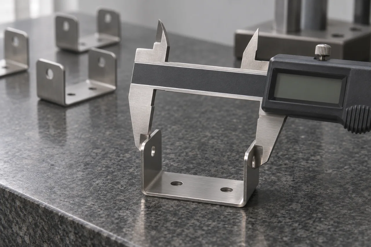
Use a complete assembly check for samples
Review individual panel dimensions first, then check the relationships that emerge when the housing is assembled. Confirm the mounting pattern, cover alignment, internal clearances, hardware location, thread access, and the specified joining details. Use the buyer's fixture or mating equipment information where it defines the interface. Record any restraint or assembly sequence used during measurement.
Keep sample identity connected to the bill of materials, drawing revisions, material specification, finish, and inspection results. Add the approved appearance reference and assembly findings. This gives engineering and quality a shared record: the panels satisfy their own definitions and the completed enclosure follows the intended equipment interface.
03 / Production route
From the first drawing to the next release.
- 01
Establish the complete assembly
Review the equipment interface, enclosure model, bill of materials, panel drawings, hardware, and supplied accessories. Define the housing datums and identify the mounting, cover, access, and appearance requirements.
- 02
Plan cutting, bending, and joining
Connect profiles with bend order, tooling access, joints, and hardware insertion. Review which interfaces are checked after forming and which are approved in the assembled condition. Keep proposed drawing changes visible.
- 03
Complete hardware and finish approval
Confirm installation orientation and thread access, then review coating, masking, visible faces, and final clearances. Inspect the completed sample from the assembly datums and record the specified mating and cover checks.
- 04
Organize the delivered housing
Release the accepted bill of materials, drawings, finish, hardware, inspection, and packing references. Identify housings and loose accessories clearly and carry the approved package into recurring batch orders.
04 / Quality & acceptance
Give engineering and receiving the same reference.
| Control point | What defines approval |
|---|---|
| Assembly datums and interfaces | Check equipment mounting points, cover relationship, internal clearances, and access features from the agreed assembly references. Record the measurement restraint or assembly sequence used where it defines the final condition. |
| Formed panels and joints | Confirm material, thickness, bend relationships, specified joining details, and any required cleanup. Keep panel revisions aligned with the assembly definition and check interfaces affected by the forming and joining sequence. |
| Hardware and final coating | Verify specified hardware, position, orientation, accessible threads, masking, coating, and visible surfaces. Check fits and clearances in the final delivered condition with the approved appearance reference. |
| Complete package and records | Match the housing and accessory contents to the bill of materials. Identify part numbers, revisions, quantities, inspection and material or treatment records, and the packing needed to protect protruding hardware and finished faces. |
05 / Results & repeat supply
Connect the engineering work to purchasing value.
Manufacturing performance benchmarks for sampling, production and final acceptance.
- Comprehensive cost
- 15–30% lower
- Shared finished-scope cost-improvement baseline
- Assembly efficiency
- 35%+
- Shared assembly improvement baseline
- Lead-time improvement
- 25–40%
- Shared delivery improvement baseline
- First-pass inspection
- 99.7–99.9%
- Shared production quality baseline
The shared program baseline uses a 3–7 day sample turnaround and a 12–20 day recurring batch-production window. The lead-time improvement range is 25–40%. For the equipment enclosure, those planning references are connected to panel production, joining, hardware installation, final coating, and complete assembly approval rather than treating each process as a separate purchase.
The commercial baseline combines 15–30% comprehensive cost reduction with 35%+ assembly-efficiency improvement. Quality planning uses 99.7–99.9% first-pass inspection, a 0.1–0.25% batch defect range, and 100% conformity with the drawing dimensions at final acceptance. The first approved housing becomes the reference for long-term repeat batches with controlled hardware, coating, inspection, and packing.
A complete enclosure brief lets purchasing compare a usable housing rather than a collection of disconnected operations. The quotation can show panel work, forming, joining, hardware, finishing, inspection, packing, and any dedicated fixture separately. Engineering evaluates the assembled fit while quality sees the checks that release it. The buyer has a clear basis for comparing sample and recurring quantities.
The same assembly reference supports first-order approval and long-term batch reorders. Keep the model, bill of materials, panel revisions, hardware specification, finish, cover fit, and packing method connected. Recurring supply can then follow an accepted housing definition while revised quantities, delivery arrangements, and approved design changes remain visible to everyone involved in the purchase.
Customer feedback
Buyer feedback is summarized around stable assembly tolerances, quick clarification of panel and hardware questions, and a complete route for addressing the quality and delivery concerns that prompt a supplier review. The enclosure discussion keeps cover fit, installed hardware, coating, and the organized receiving package in the same conversation.
06 / Project questions
Before you quote a similar component.
Is a flat DXF enough for an enclosure quotation?
Provide the formed drawings and assembly model as well as the available cutting files. The full package explains bend direction, panel relationships, mounting datums, hardware, cover alignment, and installed clearances. Keep revisions consistent so cutting, forming, finishing, and final assembly follow one housing definition.
How should we specify installed hardware?
List each fastener, insert, nut, or standoff in the bill of materials, with thread, position, orientation, and installation side. Identify supplied-installed, loose, and buyer-provided items. Include the functional requirements and check method, and review insertion access and the sequence relative to joining and coating.
What should be checked on the final sample housing?
Check the assembly datums, equipment mounting, cover fit, internal clearances, installed hardware, thread access, joints, and final finish. Use the agreed fixture or mating information where it establishes the interface. Connect the results and approved appearance reference to the same model, bill of materials, and sample identity.
Can the quotation distinguish panels from a completed housing?
Yes. State the deliverable you want priced and identify the included assembly, hardware, loose accessories, finish, inspection, and packing. Separate setup or dedicated fixture charges from recurring work. Use the same delivery scope for each quantity option to make the purchasing comparison useful.
07 / Your project
Quote the housing your equipment team needs to receive.
Bring the assembly model and bill of materials, identify the critical cover or mounting interface, and include material, hardware, finish, and quantities. Connect the panels and operations into one complete enclosure review.
- Complete enclosure model, bill of materials, and equipment mating arrangement
- Individual formed drawings and available cutting files with aligned revisions
- Material and thickness, joints, hardware specifications, and supplied accessories
- Finish reference, masking, visible faces, critical clearances, and inspection requirements
- First and repeat quantities, complete delivery scope, packing needs, and destination