Industrial equipment / mounting interfaces
A Stamped Mounting Bracket That Fits the Assembly
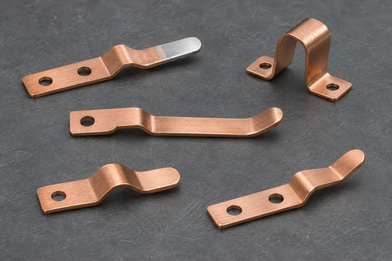
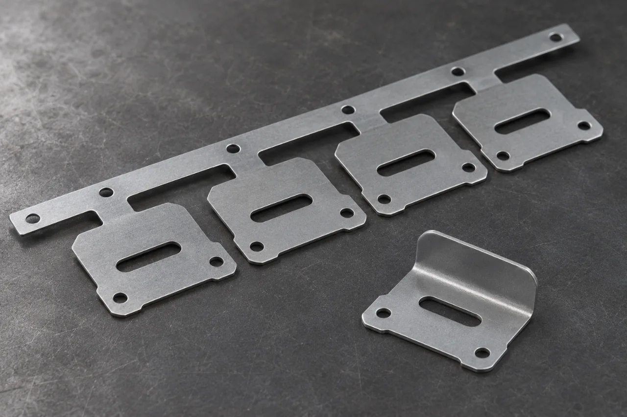
A bracket earns its place when the assembly team can install it without adjusting the surrounding equipment. This engineering case follows an industrial mounting bracket from its locating features to the finished part, connecting stamping, forming, surface treatment and inspection around the same assembly requirement. The starting question is direct: which faces and holes make the bracket work, and how will the receiving team approve them? Every review links the drawing, approval evidence and purchase scope to that practical installation.
- Customer
- Industrial equipment OEM
- Component
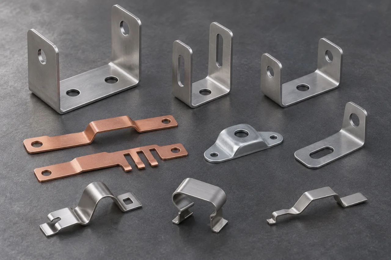
- Formed mounting bracket with locating holes and an assembly flange
- Manufacturing route
- Metal stamping, forming, edge preparation and surface finishing
- Material
- Sheet steel or stainless sheet selected for the assembly environment
01 / The challenge
Make the requirement work in the real assembly.
A bracket can match its flat drawing and still require adjustment at the assembly station. The purchasing brief must establish how the part seats, how the holes locate and which dimensions remain functional after bending and coating. Those relationships decide whether the delivered component supports a smooth build.
The project also needs a route that fits its release pattern. Purchasing must compare one-time tooling with the complete recurring part scope, while engineering defines what must remain consistent. The review brings those decisions together before sample approval, so the next order follows a component specification that both teams can use.
- Assembly job
- Locate a component on industrial equipment using defined seating faces, a formed flange and a controlled mounting-hole relationship.
- Manufacturing scope
- Compare dedicated stamping with cutting and bending, including edge preparation, finishing and any secondary features in the same delivered-part scope.
- Approval focus
- Use the installed datums to check holes and formed geometry in the specified finished condition, with the accepted sample tied to its drawing revision.
- Repeat supply
- Carry material, finish, inspection and protective packing into later releases, with changes identified against the approved baseline.
02 / Engineering approach
Turn the difficult details into a manufacturing plan.
Start with the installed bracket
The project centers on a formed sheet metal bracket that locates another component on industrial equipment. A base seats against the machine structure, one flange establishes the component position, and mounting holes connect the two interfaces. The useful specification therefore extends beyond the cut outline. It needs to show the locating arrangement, the formed height and the relationship between holes after bending, together with the material and final surface condition.
Review the bracket drawing beside a mating view or an installation section. Identify which fastener locates the part, which hole provides clearance and where adjustment is intentional. Establish whether a formed flange seats against another face or remains free. These choices let the manufacturing review concentrate control where it supports installation, giving purchasing an acceptance basis that can be explained to both suppliers and the receiving team.
Build the material and finish into the forming route
State the sheet grade, thickness and condition before selecting the die concept. Review the bend radius, flange length, grain direction where specified and the access required for each forming operation. Where a feature can move without changing the function, discuss that option while the design is being reviewed. A drawing decision made before tool construction can simplify the route more effectively than a late change to an approved die.
The finish belongs in the same plan. Identify the visible faces, protected mounting surfaces and any areas that must remain clear for threads or electrical contact. State whether functional dimensions apply to the plated or coated part. Mark burr direction and the edges that need preparation. The result is one complete part definition covering the pressed shape, subsequent operations and condition presented to assembly.
Choose the route around the release pattern
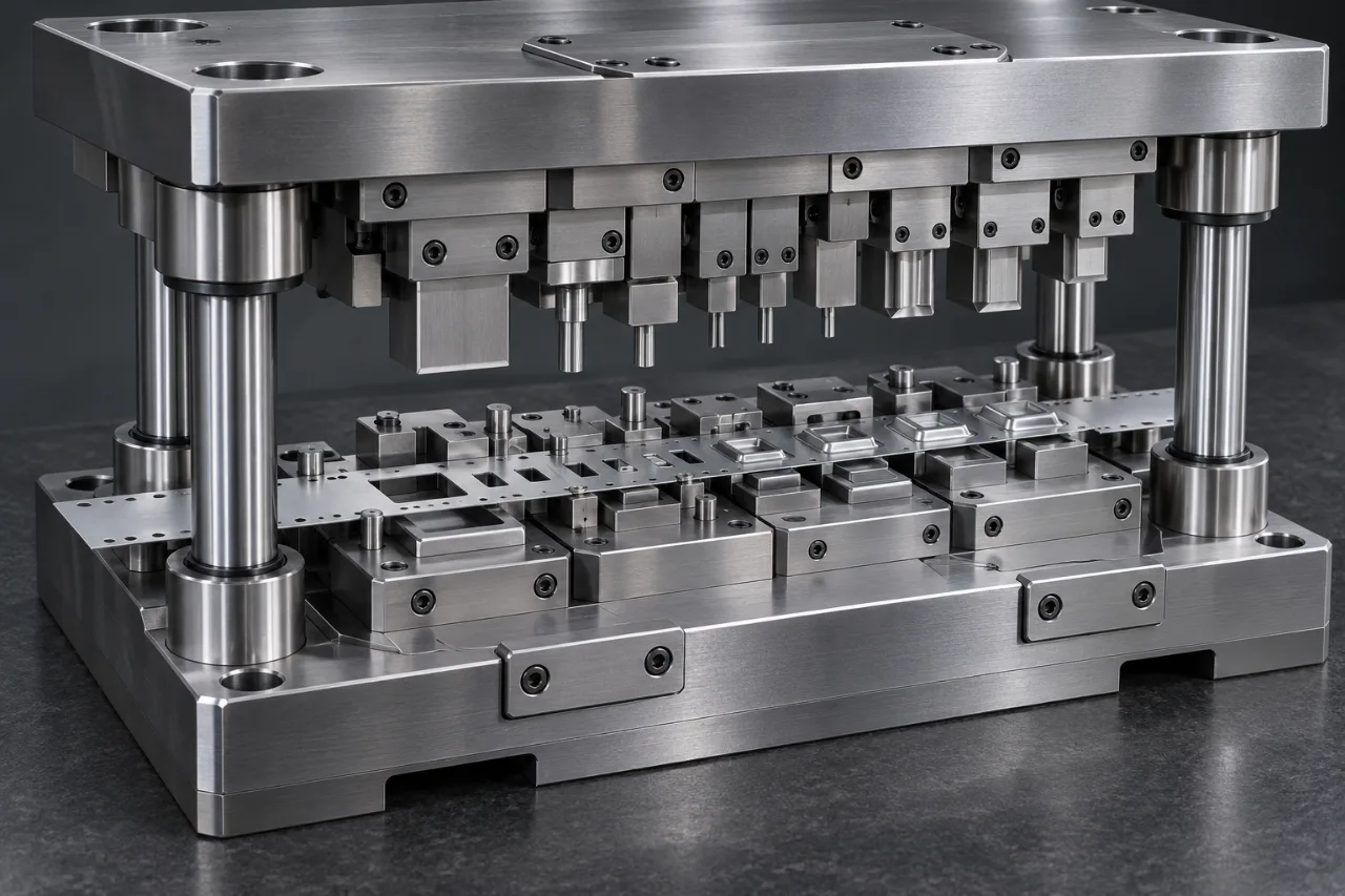
Compare a dedicated stamping route with cutting and bending using the same released geometry, finish and approval requirements. A development drawing with several planned revisions may benefit from a flexible route while the assembly is being evaluated. A stable design ordered repeatedly may justify stage tooling or a progressive concept. The useful comparison includes tooling investment, expected releases, material utilization, handling and any secondary operations required to reach the finished bracket.
Keep one-time die development separate from recurring part price. Identify trial samples, inspection reports, fixtures and finish in the proposal instead of relying on an undefined sample allowance. Include the anticipated release pattern with the first order quantity. Purchasing can then compare how each route serves the program rather than selecting a piece price that excludes part of the work needed for installation.
Approve the relationship between the holes and the bend
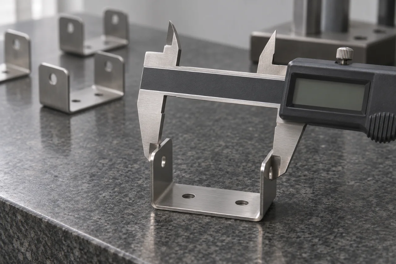
The sample plan should begin with the assembly datums. Check the mounting-hole pattern from the defined references, then evaluate formed height, flange position and any specified angle or geometric relationship. Where a fixture represents the installed position, agree what the fixture establishes and how the result is recorded. An assembly check complements the dimensional report by showing how the accepted bracket interfaces with the mating component.
Check the bracket in the condition specified for approval. That may mean after deburring and coating, with particular mounting faces protected as defined on the drawing. Keep material identity, finish reference, part revision and measured sample identification together. Record open drawing clarifications separately from tool corrections, then close them against the next agreed sample. The approval record becomes a usable baseline for the next release.
Carry the approved condition into repeat orders
Repeat production needs the same references that support sample approval: a controlled drawing, material condition, finish, critical-feature list and accepted sample reference. List any engineering change separately and identify the release at which it applies. A changed flange, hole or coating should lead to an explicit review of the affected interfaces. This keeps purchasing, production and receiving inspection aligned on the component being ordered.
Packing supports that baseline. Formed flanges need separation and support where contact between parts can mark a visible surface or alter a thin feature. Agree orientation, part labels and lot identification with the receiving requirements. Include the destination and delivery basis in the quotation. The manufacturing scope then extends to an identifiable finished bracket prepared for the next assembly operation, with the required records accompanying the shipment.
03 / Production route
From the first drawing to the next release.
- 01
Define the assembly
Mark the mounting datums and provide the mating view with the controlled part drawing. State which holes locate, which allow clearance and how the flange establishes the installed component position.
- 02
Review the complete route
Connect blanking, piercing, forming, edge preparation and finish to the same final condition. Compare route choices using the first release, repeat forecast and planned revisions.
- 03
Approve a finished sample
Check the functional hole-to-flange relationship, formed dimensions, material and surface against the agreed specification. Link the sample identity to the inspection and assembly checks.
- 04
Release the repeat package
Carry the accepted revision, sample reference, inspection scope and packing requirements into the next purchase release. Identify any later engineering change explicitly.
04 / Quality & acceptance
Give engineering and receiving the same reference.
| Control point | What defines approval |
|---|---|
| Mounting relationship | Functional holes and seating faces checked from the assembly datums in the specified formed condition. |
| Material and finish | Sheet grade, thickness, condition and treatment connected to the purchase specification. |
| Edges and appearance | Burr direction, prepared edges and visible faces evaluated against the agreed criteria. |
| Delivery condition | Part labels, packing orientation and protective separation matched to the receiving requirements. |
05 / Results & repeat supply
Connect the engineering work to purchasing value.
Manufacturing performance benchmarks for sampling, production and final acceptance.
- Drawing conformity
- 100%
- Drawing-dimension conformity at final acceptance
- Production window
- 12–20 days
- Repeat production window
- Overall cost reduction
- 15–30%
- Comprehensive manufacturing cost reduction range
- Assembly efficiency
- 35%+
- Assembly-efficiency improvement baseline
The manufacturing baseline combines 100% drawing-dimension conformity with a 12–20 day repeat-production window. Sample turnaround follows a standard 3–7 day range. These measures connect the approved bracket specification to a defined delivery rhythm, with the material, finish and inspection requirements carried through the same order package.
The improvement baseline includes a 15–30% reduction in comprehensive cost and an assembly-efficiency improvement of 35% or more. Keep the complete supplied component, finishing, inspection and assembly work in the comparison so the commercial decision reflects the bracket as it is purchased and installed. Following first-order approval, the supply relationship continues through long-term repeat releases.
The buying objective is an approved bracket specification that connects the tooling route to the installed assembly. A clear datum scheme, finished-condition sample and complete commercial scope help the team make a sourcing decision it can repeat. Bring the mating view with the part drawing so the review starts with the interface that does the work.
A practical quotation identifies the tooling investment, finished-part operations, approval work and delivery basis separately. Purchasing can see what is included, engineering can connect that scope to the mating requirements, and receiving inspection can work from the same accepted condition. That shared reference is useful when reviewing a repeat release or a proposed drawing change.
Customer feedback
Customer feedback emphasizes stable tolerances and responsive communication, with support addressing earlier supplier yield and delivery issues. For the mounting-bracket program, that feedback aligns with the purchasing priorities in this case: a consistent assembly interface, a clear approval reference and an established path from the first order into continuing batch supply.
06 / Project questions
Before you quote a similar component.
Should all bracket dimensions have the same tight tolerance?
Identify the dimensions that control location, fit and seating, then specify their datum references and acceptance condition. Surrounding dimensions can follow the agreed general drawing requirements where appropriate. This lets the review put control where it supports the installed component.
What helps when a formed bracket does not fit an existing assembly?
Send a mating view and mark the interface that does not align. Include the current part revision, measured condition and finish state. The manufacturing review can then focus on the locating scheme and the relationship between the cut and formed features.
Does coating belong in the bracket approval plan?
Yes. Specify the final surface condition and whether the functional dimensions apply before or after treatment. Identify masking and the surfaces that locate the bracket. The sample and inspection plan can then evaluate the same condition that the assembly team receives.
What should I include to compare stamping with cutting and bending?
Use the same drawing revision, material, finish, quantities, inspection and packing scope. Ask for tooling and recurring part costs separately, with trial deliverables defined. Include the repeat forecast and known revisions so each proposed route is assessed against the same program.
07 / Your project
Bring the bracket. Show us where it fits.
Send the formed drawing, mating view and expected releases. Start a manufacturing review around the mounting relationship, finished condition and complete supply scope.
- Controlled part drawing and formed CAD model at matching revisions
- Mating view with locating faces, mounting holes and installed position
- Material grade, thickness, condition, finish and edge requirements
- First release quantity, repeat forecast and planned drawing changes
- Critical-feature inspection, approval samples, packing and destination