Tooling and equipment / supporting CNC interfaces
CNC Locating Components for Tooling and Equipment
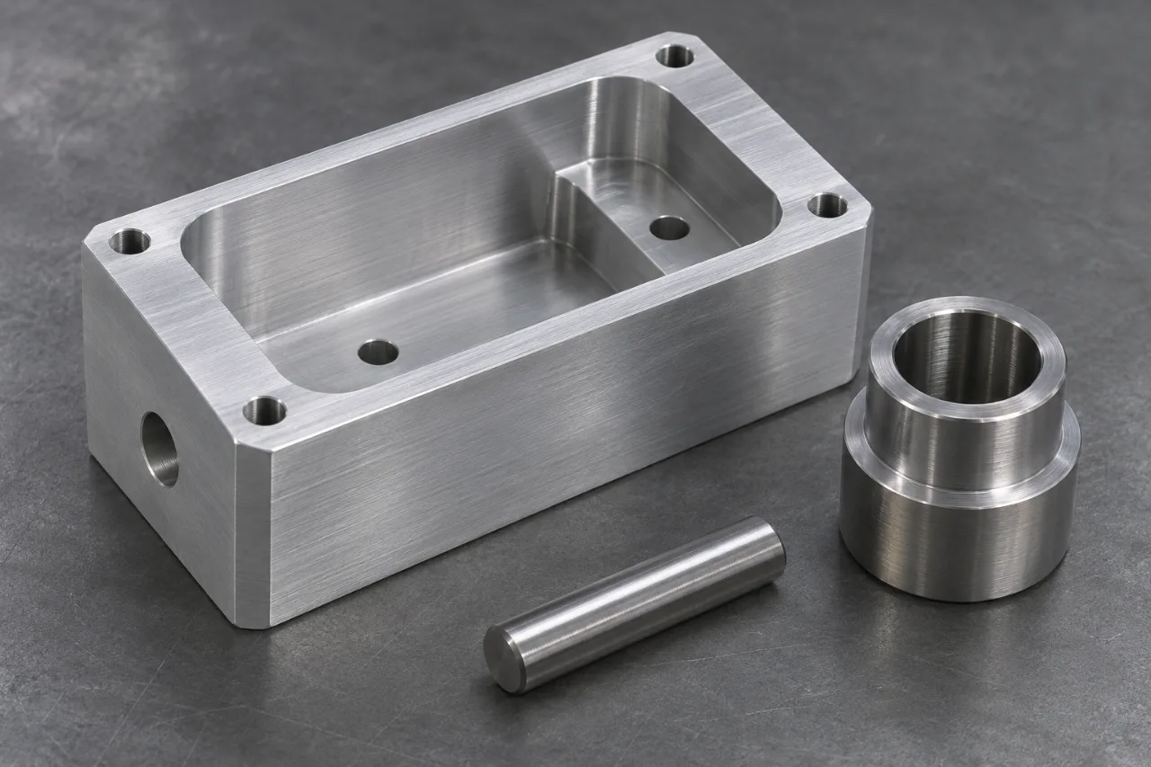
A locating block, bushing, or mounting interface carries the relationships that connect an assembly. This project treats supporting CNC work as a fit and datum problem first, then follows material, setups, hole production, surface treatment, inspection, and delivery. Give each tight requirement a role in the assembly. Show what locates, what clamps, and which features must fit after treatment. Connect the machining route and inspection scope with the finished component your buyer intends to approve, install, and reorder with confidence.
- Customer
- Stamping tooling and industrial equipment OEM
- Component
- Machined locating block, mating bushing, and mounting components
- Manufacturing route
- Supporting CNC milling and turning, surface treatment, deburring, and final inspection
- Material
- Drawing-defined aluminum, carbon or alloy steel, and stainless steel
01 / The challenge
Make the requirement work in the real assembly.
The application combines drawing-defined locating and mounting components for tooling or equipment. A block may establish a mounting plane and locate pins; a turned component may connect a bore and shoulder; threaded features may secure the interface to the larger assembly. Send the mating arrangement with each individual drawing so the manufacturing review can identify which relationships carry the function.
Define the surfaces that locate the part and the feature that establishes orientation. Keep those datums consistent with the inspection setup. Highlight the holes, shoulders, contact faces, and threads that control assembly, then separate them from nonfunctional clearance features. This directs the quotation and machining plan toward the characteristics your tooling or equipment actually uses.
- Application
- Machined locating and mounting components establish the interfaces within stamping tooling, fixtures, or related industrial equipment.
- Main requirement
- Control the relationship between functional datums, locating holes, bores, shoulders, threads, and the final mating condition.
- Supply scope
- Drawing-defined milled or turned parts with specified material, treatment, edge preparation, inspection, identification, and packing.
- Approval reference
- Controlled component drawings, mating information, final acceptance condition, and actual inspection results referenced to the datum system.
02 / Engineering approach
Turn the difficult details into a manufacturing plan.
Translate mating requirements into controlled features
Identify the fit expected at each locating hole, pin, bore, or shoulder. Provide the drawing limits and geometric controls that define the relationship, along with the applicable units and drawing standard. Add the mating component information where it explains the fit. The review can then connect a functional requirement to a measurable feature instead of treating a tight tolerance as a general quality statement.
Include the final surface condition in the requirement. If a component receives treatment after machining, state which limits apply to the delivered part and which surfaces are masked or finished afterward. Keep threads and bores within this review. A useful specification defines what the assembly team receives rather than leaving the acceptance stage to interpretation.
Choose material for the interface and its process route
Specify the material grade, starting condition, and any required treatment or material documentation. Review those inputs alongside the component geometry and function. Aluminum housing features, steel locating parts, and wear-related components can require different manufacturing sequences and surface conditions. Keep each item defined in the bill of materials so a shared assembly does not blur separate material requirements.
Where a material or treatment option is open, explain the functional reason and identify who approves the selection. Compare the finished route, including heat treatment where specified, surface finishing, final machining, and inspection. Show the alternatives separately in the quotation. The purchasing comparison can then connect each cost to the interface and acceptance scope it supports.
Plan workholding around the critical relationships
Review the surfaces used to hold and locate the component at each machining stage. Establish how critical hole and face relationships are carried across setups. Consider tool access, pocket depth, internal corner geometry, thin sections, and the features available for stable clamping. Discuss design details that are open for manufacturability review while preserving the mating requirements that are fixed.
For turned parts, connect the bore, outside diameter, shoulder, and threaded features to their functional axis and inspection references. For milled parts, connect mounting planes, locating holes, and pockets to the defined datum system. The objective is a process plan in which machining access and measurement access support the same final geometry.
Give holes and threads their complete definition
A hole can act as clearance, a locating interface, a bearing surface, or part of a threaded connection. State its intended role and drawing requirement. Include depth, entry features, thread specification, engagement requirements, and the relevant inspection condition. Use section views where a model alone leaves the feature difficult to interpret. Keep related hole positions and datum references visible together.
Review edge preparation at entrances and functional shoulders. Identify corners that must remain defined and edges that need a controlled break. Include any masking, protection, or final operation needed after treatment. When a gauge or mating check forms part of acceptance, provide its reference and method so the sample plan can connect geometric results to the intended assembly.
Approve the component after the specified treatment
Build the sequence around the final requirements. Heat treatment, coating, surface finishing, and any subsequent machining need to be considered with the fit surfaces and locating features. State the final condition for critical measurements and identify which process records belong with the order. Keep optional finishing work distinct so the quotation describes the actual delivered component.
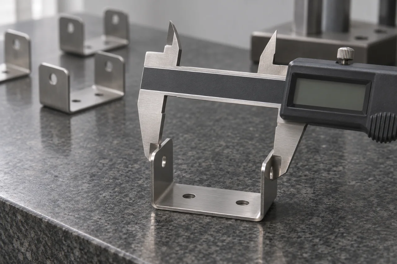
Use production-intent samples to evaluate the drawing-controlled relationships in that final state. Check the mounting face, locating features, bores, threads, and agreed mating fit from the specified datums. Record the sample identity, method, actual results, and condition. An approval based on the finished interface gives later releases a useful reference.
03 / Production route
From the first drawing to the next release.
- 01
Review the locating scheme
Read the component and mating drawings together. Identify functional datums, locating and clearance features, fits, threads, and acceptance stage. Connect each critical requirement to the interface it establishes.
- 02
Plan material and setups
Review material condition, treatment sequence, workholding, tool reach, and datum transfer. Keep critical hole and face relationships visible across milling or turning setups and clarify geometry open to manufacturing review.
- 03
Finish and measure the interface
Complete the specified treatment and any subsequent operation, then inspect critical relationships in the defined final state. Record sample identity, actual values, method, material and treatment references, and the agreed mating check.
- 04
Carry the reference into repeat work
Release the accepted drawings, material, finishing, critical feature list, inspection, and packing together. Preserve identification for mating components and connect recurring orders with the approved tooling or equipment interface.
04 / Quality & acceptance
Give engineering and receiving the same reference.
| Control point | What defines approval |
|---|---|
| Functional datum relationships | Inspect locating holes, mounting planes, bores, shoulders, and other critical features from the specified datum system. Use the defined restraint or fixture and relate the results to the component's intended mounting arrangement. |
| Holes, threads, and mating fit | Check drawing-defined fit, feature depth, entry condition, threads, engagement details, and the agreed gauge or mating method. Distinguish functional locating features from clearance holes and record the specified inspection condition. |
| Final material and surface state | Confirm material grade and condition, specified treatment, masking, final machining, and controlled edge preparation. Evaluate critical dimensions in the state required by the delivered-part drawing. |
| Report and protected delivery | Connect part and revision identity with actual results, sample or lot reference, material and treatment records, and package quantity. Separate finished fit surfaces and protect external threads and locating features in the agreed packing. |
05 / Results & repeat supply
Connect the engineering work to purchasing value.
Manufacturing performance benchmarks for sampling, production and final acceptance.
- Final dimensions
- 100%
- Drawing-dimensional conformity at final acceptance
- First-pass inspection
- 99.7–99.9%
- Shared production quality baseline
- Lead-time improvement
- 25–40%
- Shared delivery improvement baseline
- Batch defect range
- 0.1–0.25%
- Shared batch quality baseline
The standard program baseline pairs a 3–7 day sample turnaround with a 12–20 day recurring production window and a 25–40% lead-time improvement range. For the CNC locating interface, planning connects material, setups, treatment, any final machining, and inspection of the finished fits. Sample approval establishes the reference used for the first production order and subsequent batch releases.
The shared quality baseline is 99.7–99.9% first-pass inspection, a 0.1–0.25% batch defect range, and 100% drawing-dimensional conformity at final acceptance. Commercial planning uses the shared 15–30% comprehensive cost-reduction and 35%+ assembly-efficiency baselines. Long-term repeat purchasing follows the approved locating scheme, final surface condition, measurement method, and protected delivery package.
Supporting CNC work is easier to buy when each tolerance has a visible function. The complete quotation connects material, machining setups, finishing, final operations, inspection, and packing with the locating scheme. Engineering can preserve the mating requirements while purchasing compares a defined finished component. The discussion stays focused on the fit and records the tooling or equipment needs.
A controlled interface also supports first-order approval and long-term repeat batches. Keep the accepted datum scheme, feature limits, material condition, treatment, inspection setup, and mating references connected to the part number and revision. Quantity and schedule discussions can then use a stable definition of what the receiving team will inspect and place into the assembly.
Customer feedback
The feedback summary centers on stable tolerances, prompt engineering responses, and practical resolution of quality-yield and delivery concerns in a supplier transition. For locating components, that means a clear datum scheme, consistent finished fits, inspection records that match the drawing, and a dependable reference for repeat orders.
06 / Project questions
Before you quote a similar component.
How do we identify the dimensions that deserve close control?
Start with the surfaces that locate the component and the features that establish the mating fit. Mark their datum relationships, limits, and geometric requirements on the drawing. Separate functional features from clearance geometry and provide the mating information that explains the intended assembly.
Should critical fits be specified before or after treatment?
State the acceptance stage on the drawing and identify the final delivered condition. Include masking, subsequent machining, and controlled edge preparation where specified. The quotation and sample plan should follow that complete sequence, with critical fit measurements recorded in the required finished state.
What helps with a component that needs more than one setup?
Provide the complete datum scheme and highlight the relationships between critical faces, holes, and axes. The machining review can then address workholding, datum transfer, access, and inspection together. Identify features that can change for manufacturability and keep fixed mating requirements clearly marked.
Can CNC parts remain part of a larger stamping or tooling project?
Yes. Keep each component's drawing, part number, material, treatment, and inspection requirements distinct, then connect it to the assembly or tooling scope. Identify any mating check and supplied accessories. The quotation should show the supporting CNC work while preserving the complete project's approval and delivery references.
07 / Your project
Make the locating scheme the start of your CNC review.
Send the part and mating drawings, mark the datums and final fits, and include material, treatment, quantities, and inspection needs. Put the finished tooling or equipment interface at the center of the quotation.
- CAD, controlled drawing, mating view, and tooling or equipment context
- Material grade and condition, treatment, masking, and finished acceptance stage
- Functional datums, hole and bore fits, threads, critical relationships, and mating checks
- Inspection scope, report format, identification, and protective packing requirements
- First-order and repeat quantities, required milestone, complete supply scope, and destination