
Skip to content

CNC machining / turning

CNC Turning for Shafts, Bushings & Round Parts

CNC turning makes shafts, sleeves, bushings and threaded bodies by rotating stock against a cutting tool. WenXinDa helps OEM buyers source turned metal components with the diameters, shoulders and bores needed for reliable assembly. For parts with flats, keyways or cross-holes, the turning and milling steps are planned together around the functional axis.

Process at a glance

Why rotational geometry changes the route

Turning forms diameters and shoulders around an axis. Bores, grooves and threads may follow in sequence. Off-axis flats or holes can introduce a second operation, so the complete feature set is more informative than an isolated diameter callout.

The operation creates the geometry; the part function determines which features need the closest control.

CNC machining A rotating cutter removes material from a fixed workpiece to form pockets and other features. CUTTERWORKPIECE01 / REMOVE
CNC machining

01 Fit

Turning for parts built around a central axis

Turning is a natural starting point when diameters and shoulders do most of the work. The key is to define how the bore, outside diameter and end faces relate to the bearing, seal or mating component.

Shafts and pins

Stepped diameters, shoulders and grooves can locate bearings, seals and retained components. End features may require a secondary setup.

Bushings and sleeves

An inside diameter and outside diameter often work as a pair. Wall thickness and concentricity matter more than nominal diameter alone.

Threaded bodies

External or internal threads should include form, pitch, engagement length and the mating component. Surface treatments can change fit.

Design review

Control the axis, not just the size

A shaft can be the right diameter and still cause an assembly problem if its journals do not run together. Mark the datum axis, shoulders, surface texture and runout relationships that determine how the part rotates or locates.

  • Specify the thread standard, class, handedness and usable length, including any relief needed at a shoulder.
  • Identify the sealing seat or shoulder that controls axial assembly, and distinguish it from a clearance surface.
  • Identify which diameter or bore establishes the datum axis for inspection.
  • State fits and surface texture only where they are functionally needed.
  • Include groove widths, edge reliefs and chamfers that matter to assembly.
  • Specify thread standard and any gauge or mating requirements.
  • Show cross-holes, milled flats and keyways so secondary operations are included in the route.
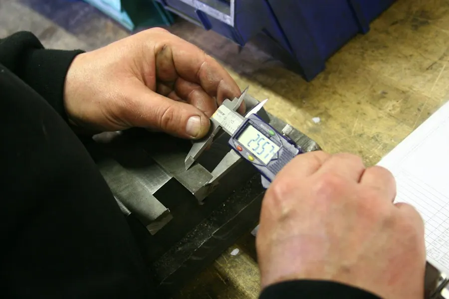
Measuring a metal feature with a digital caliper
Measurement requirements follow the functional axisProcess detail

02 Decisions

Turning decisions that shape the quote

Stock diameter, grip length and support determine how a turned part can be held. Secondary holes, flats and heat treatment then shape the route to the finished component.

DecisionWhat to specifyWhy it matters
Secondary featuresFlats, keyways, cross-holes and their angular relationship to the main axisTurning and milling should use a connected datum strategy when the round part must also orient in an assembly.
Heat treatment and finishRequired final condition, machining allowance and surfaces accepted after treatmentThe sequence affects which dimensions are finished and measured before the part is ready to ship.
StockBar grade, condition and diameterMaterial availability and waste change the starting route.
Long or thin geometryLength-to-diameter relationship and straightness needSupport and deflection can affect machining and inspection.
Bore and OD relationshipDatums, fit and runout requirementsThese establish the sequence and the right measuring approach.
Secondary featuresFlats, cross-holes, slots and heat treatmentThe full route may extend beyond turning.

03 Project route

A turning project, step by step

Start with the fit the part must deliver. That guides stock selection, the order of turning operations and the features to measure after finishing.

  1. 01

    Define the function

    Share the mating part or explain the fit, load and motion the part must support.

  2. 02

    Confirm the route

    Review bar stock, workholding, operations on each end and any cross features.

  3. 03

    Approve measurements

    Agree the inspection method for diameters, bores, threads and runout.

  4. 04

    Protect the part

    Specify how finished surfaces and threads should be protected in packing.

04 Applications

Turned parts for motion, location and connection

Shafts locate bearings, sleeves maintain spacing, and threaded bodies join components. Their geometry is similar, but the critical interface is different.

Stepped shaft for a locating assembly

Project brief: a shaft includes multiple diameters, a shoulder and a cross-hole or flat. Identify the functional axis, bearing or locating seats and the axial stack from the shoulder. Review groove access, thread runout and the sequence for secondary milling. The first-part check can then connect diameter size, runout and shoulder position to the way the shaft locates in the complete assembly.

Bushing with a controlled bore

Project brief: a sleeve needs an internal running or locating surface and an outside diameter that fits another component. Show the mating materials, the intended fit and the accepted surface condition. Review bore depth, wall thickness and clamping around the finished geometry. If a coating is specified, define the final dimensional state and masking areas. A useful quotation covers the finished bushing and the inspection required for its actual interfaces.

Threaded adapter with sealing features

Project brief: a turned adapter combines a thread, shoulder and sealing seat, with wrench flats added for assembly. Provide the exact thread standard and identify the face or feature that seals. Review the relationship between the axis, thread and seating geometry together. Add any coating, thread-gauging and protective packing requirements so the part arrives with the same functional surfaces used for sample approval.

Include both turned and milled features in the first enquiry. Planning them together helps preserve the relationship between the main axis, mounting flats and cross-holes.

Application project brief

See the part.
Plan the details that matter.

Use the application, mating features and approval checks to turn a drawing into a clear manufacturing brief. Bring your part number and the assembly requirement that drives the design.

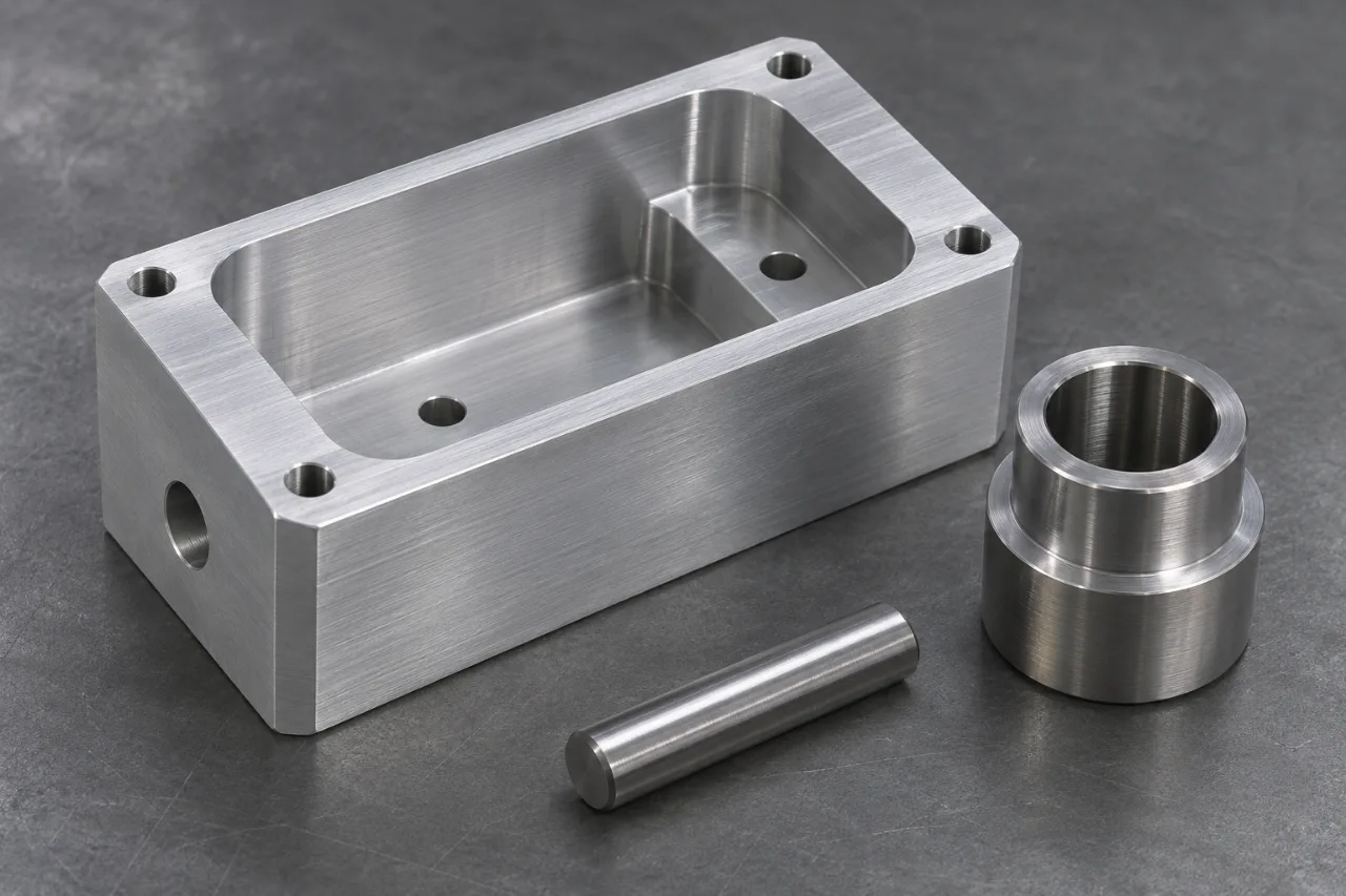
Machined aluminum housing, turned steel bushing and dowel pin
Milled and turned features for assembly interfaces

Tooling & equipment / supporting CNC parts

Keep mating features on the same page.

A machined locating block, fixture component or mounting interface often carries the dimensions that connect several parts. A tight tolerance has value when it protects the intended fit. The review starts with the locating scheme, access for machining and the final inspection condition, connecting the part drawing to the assembly task.

The objective is a supporting component with a clear fit requirement and a proportionate inspection plan. Mark the mating features when you request a quote so the review targets the dimensions that do the work.

Explore the project approach

Engineering approach

  • Review the model and drawing together. Establish the datum features, mating holes, threads and surfaces that control position or alignment.
  • Plan setups around tool reach, workholding and the relationship between critical features. Discuss corner radii and deep features that affect the machining route.
  • Include material condition, surface treatment, masking and deburring in the same plan. Define whether critical dimensions apply before or after treatment.

Approval checkpoints

  • Inspect the critical relationships from the specified datum system.
  • Check thread requirements, accessible edges and mating surfaces.
  • Link inspection records and part identification to the drawing revision.

05 Common questions

Questions before you request a quote

Straightforward answers to the design, manufacturing and purchasing questions that come up before an order.

Should I specify a fit or only a nominal shaft diameter?

A functional fit needs an agreed size range and a relationship to the mating component. Mark the locating or bearing diameter, relevant geometric control and finished surface condition. Include the mating drawing when the fit is being developed so the turning review addresses the assembly requirement.

Can a turned part include flats and cross-holes?

Yes. Include those features in the same model and drawing as the turned diameters. Define their angular and positional relationships to the main axis. The complete part can then be planned around turning, secondary machining, deburring and final inspection together.

What is the difference between CNC turning and milling?

In turning, the workpiece rotates to create diameters, bores and shoulders. In milling, the cutting tool rotates to create pockets, faces and off-axis features. Many parts use both processes.

Can a turned part include flats, keyways or cross-holes?

Yes. Those features can be added through milling or other secondary operations. Include them in the model and drawing so their position is controlled relative to the turned axis.

How should I specify a bearing or press fit?

Show the mating diameter, fit requirement, material condition, surface texture and datum reference. Identify whether dimensions apply after coating or heat treatment. That gives machining and inspection a clear target.

What changes the price of a turned part?

Material and bar size, removed volume, slenderness, the number of setups, bore depth, threads and secondary features all contribute. Finishing and inspection requirements also affect the complete part price.

Prepare an RFQ

Request a quote for a turned component

Show the functional axis and mating fit, then include any operations that follow turning, such as milling, heat treatment or coating.

  • • 3D model and 2D drawing with datum axis
  • • Bar material, quantity and finish
  • • Fit, runout, thread and texture requirements
  • • Cross-features, inspection scope and destination
Request a quote

Explore related manufacturing routes