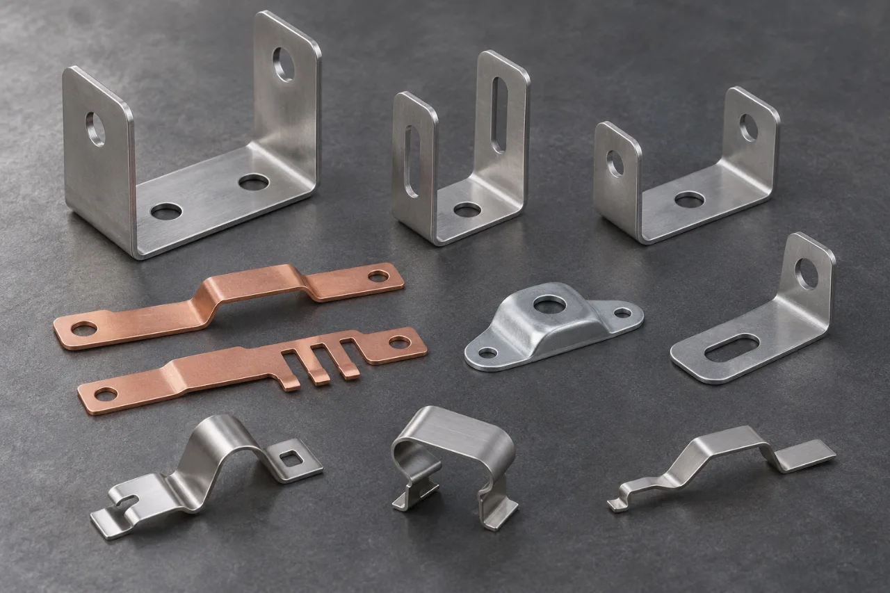
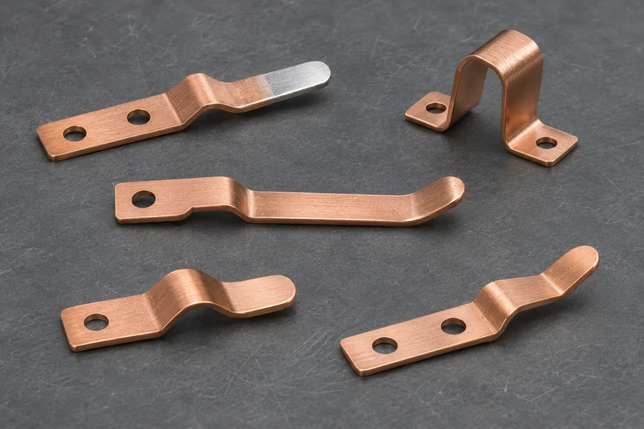
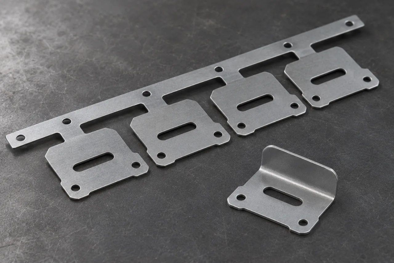
Automation equipment / formed retaining components
Spring Retaining Clip for Automation Equipment
A retaining clip earns its place in an automation assembly when it installs as intended, holds the mating component in its working position, and follows a specification that can be repeated. This project connects spring behavior with material condition, formed geometry, burr direction, and functional approval. Bring the mating view, working deflection, and repeat quantities into the review. Give purchasing a complete finished-part comparison and engineering a shared reference for the clip's installed behavior, tooling scope, inspection, and protected delivery.
- Customer
- Industrial automation equipment OEM
- Component
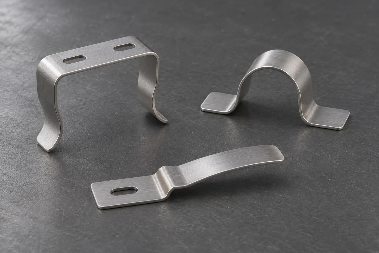
- Formed spring retaining clip
- Manufacturing route
- Metal stamping, forming, edge preparation, and functional approval
- Material
- Drawing-defined spring steel or spring-temper stainless steel
01 / The challenge
Make the requirement work in the real assembly.
The project centers on a formed metal clip that locates and retains a replaceable component inside automation equipment. The important shape is the one the clip takes in service. A free-state profile helps describe the blank and forming work; an installed view shows where the clip touches, how far it deflects, and how the retained component is released. Put both views in the enquiry so the tooling discussion follows the actual assembly task.
Identify the surfaces that locate the clip and the faces that perform the retaining work. Add the mating component, installation direction, available access, and the point where an operator or assembly fixture applies force. This gives the review a clear priority: develop the specified geometry around the working interface and establish a functional check that can accompany dimensional approval.
- Application
- A formed clip locates and retains a replaceable component inside an automation assembly.
- Main requirement
- Connect free-state geometry with installed position, working deflection, and the agreed retention and release check.
- Supply scope
- Finished stamped clips with defined material, edge preparation, finish, inspection, packing, and a separately visible die scope.
- Approval reference
- One released drawing, production-intent material, identified trial samples, and a repeatable functional test arrangement.
02 / Engineering approach
Turn the difficult details into a manufacturing plan.
Turn the spring requirement into a usable specification
Begin with the material grade, thickness, and temper, then describe the intended working deflection and the behavior your design requires there. If the clip operates through repeated movement, include the buyer's functional test procedure, loading arrangement, and acceptance criteria. Connect those requirements to the same part number and drawing revision as the dimensional specification. The functional objective belongs in the manufacturing brief from the start.
Keep installation behavior, retained position, and release behavior distinct. They describe different parts of the component's job and may involve different contact points. State how the test part is restrained, which mating geometry is used, and how results are recorded. A defined setup makes trial feedback useful for both the product engineer and the tooling team.
Choose material and forming decisions together
The alloy designation alone does not define a spring component. Thickness, material condition, grain direction, and treatment sequence influence how the formed clip reaches its working shape. Review the selected stock alongside bend radii, narrow bridges, lanced features, and the amount of forming in each area. Keep the intended production material connected to the die trial rather than evaluating geometry in an unrelated stock condition.
Where the drawing permits alternatives, compare the full route: stock, forming, any specified treatment, final surface condition, and approval work. Show each material option separately in the quotation. The purchasing team can then compare the finished requirement and recurring supply scope while engineering retains control of the properties that define the clip's function.
Put the burr on the right side of the job
Identify the edge that contacts the mating component, the edge handled during installation, and any surface that slides during release. Mark the permitted burr direction and the finished edge requirement on the drawing. A clean outline in a model does not communicate those details. An explicit edge callout lets the tool sequence, part orientation, and secondary finishing be reviewed against the same functional requirement.
Bring the final separation point into the discussion when it leaves a witness feature on the part. Review that location against the contact and handling surfaces, then include any deburring or edge treatment in the delivered scope. The objective is a clip whose edge condition supports the intended installation and mating interface, with acceptance defined before the first production-intent sample.
Develop the tool around the controlled part
Compare a staged route with progressive tooling using the stability of the drawing and the expected release pattern. Establish how the blank is carried, where the part is located during forming, and which features establish the final spring profile. Keep tool access and inspection access visible while the sequence is reviewed. Separate die development, trials, agreed corrective work, and recurring part operations in the proposal.
Use the trial plan to connect the selected material, tool revision, free-state geometry, installed check, and surface condition. Record the setup used for approval and identify the samples retained as the reference. This makes the tool investment easier to assess because the quotation describes the part it is intended to produce and the evidence used to release it.
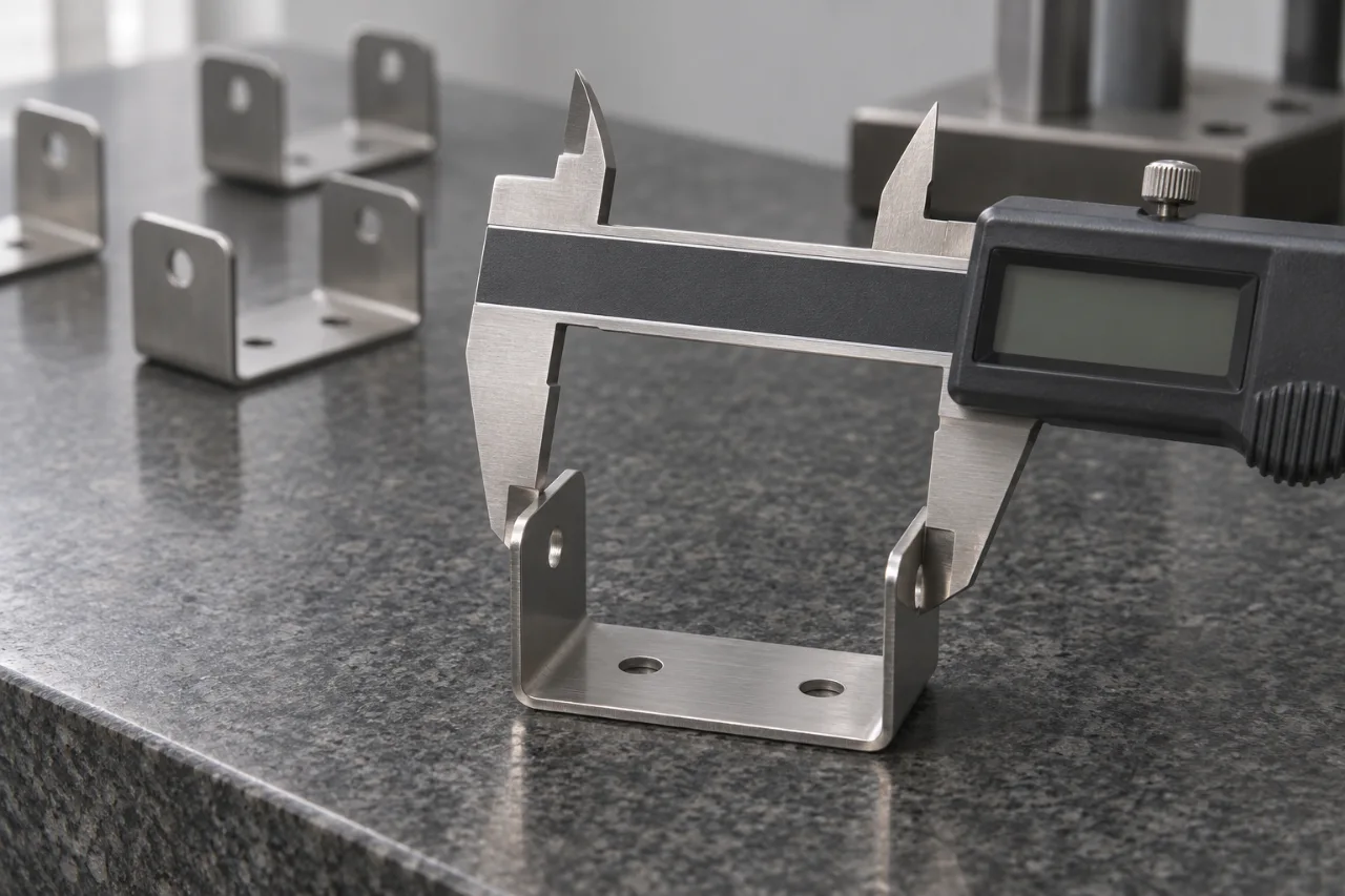
Approve geometry and behavior in a shared sequence
Start dimensional review from the features that locate the clip in the assembly. Check the formed profile, functional contact position, and other drawing-controlled characteristics in their specified state. Then perform the agreed installation and retention check using the defined mating arrangement. Record results by sample identity so dimensional findings and functional findings describe the same trial parts.
Finish approval also belongs in this sequence. Identify the specified surface treatment, areas that perform contact or sliding work, and any permitted marks. State whether functional approval applies before or after treatment. The delivered clip, the approved sample, and the inspection record should all describe the final condition your receiving and assembly teams will use.
03 / Production route
From the first drawing to the next release.
- 01
Define the working interface
Review the installed view, mating component, locating faces, working deflection, and the buyer's functional method. Separate installation, retention, and release requirements so the first tooling discussion addresses the actual assembly operation.
- 02
Review material and tooling
Connect grade, thickness, temper, grain direction, bend geometry, burr side, and final separation point. Compare staged and progressive routes against drawing stability, first-order quantity, and the pattern of repeat releases.
- 03
Trial the final component
Produce the approval reference in the specified material and finished condition. Inspect locating features and the formed profile, then perform the agreed installation and retention check on the same identified sample set.
- 04
Carry approval into repeat supply
Release the accepted drawing, material condition, tool identity, finish, functional method, and packing reference together. Keep later design changes visible and connect each recurring order to the approved part and its receiving requirements.
04 / Quality & acceptance
Give engineering and receiving the same reference.
| Control point | What defines approval |
|---|---|
| Location and formed geometry | Measure the locating features, contact position, profile, and drawing-controlled dimensions from the specified datums. State whether each characteristic is evaluated free, restrained, or installed in the defined mating arrangement. |
| Working deflection and function | Use the buyer-approved setup, load or displacement method, mating geometry, and limits for installation, retention, and release. Identify samples so functional findings can be read beside their dimensional results. |
| Material, edges, and finish | Match the specified grade, thickness, temper, treatment, burr direction, and finished edge condition. Check the working and handling surfaces in the final delivered state and retain the agreed reference. |
| Records and protected delivery | Connect the sample and lot identities with the drawing revision, inspection results, functional record, package quantity, and label. Pack formed legs and contact features so the accepted geometry is protected through handover. |
05 / Results & repeat supply
Connect the engineering work to purchasing value.
Manufacturing performance benchmarks for sampling, production and final acceptance.
- Sample turnaround
- 3–7 days
- Standard sample turnaround
- First-pass inspection
- 99.7–99.9%
- Shared production quality baseline
- Batch defect range
- 0.1–0.25%
- Shared batch quality baseline
- Assembly efficiency
- 35%+
- Shared assembly improvement baseline
The program baseline combines a 3–7 day sample turnaround with a 12–20 day batch-production window. Lead-time improvement is represented by the shared 25–40% range. For this clip application, the schedule is organized around the working-interface review, production-intent material, sample measurement, and functional approval so the trial stage establishes a useful reference for the first production release.
The shared commercial baseline includes 15–30% comprehensive cost reduction and 35%+ assembly-efficiency improvement. Quality planning pairs 99.7–99.9% first-pass inspection and a 0.1–0.25% batch defect range with 100% drawing-dimensional conformity at final acceptance. The supply model carries the first approved order into long-term repeat batches using the same controlled clip, tool, inspection, and packing references.
A complete retaining-clip brief gives purchasing a finished-part comparison instead of an isolated stamping price. Tooling, material, forming, edge preparation, finishing, inspection, and packing remain visible. Engineering can identify the features that control the installed behavior, while quality can connect the approval method to the physical parts. The commercial decision follows the component's job in the assembly.
The same reference supports the transition from the first order into long-term batch purchasing. Keep the accepted material and temper, working deflection, functional method, tool identity, and drawing revision connected to subsequent releases. A clear baseline makes it easier to discuss quantity, timing, and delivery changes while preserving the features and records that define the approved clip.
Customer feedback
Buyer feedback is summarized around stable tolerances, responsive technical communication, and a practical answer to the yield and delivery issues behind a supplier review. For the retaining clip, that discussion stays focused on the installed function, material condition, edge quality, and the approved reference used for recurring batches.
06 / Project questions
Before you quote a similar component.
Is the free-state drawing enough to review the clip?
Provide the free-state definition and an installed or mating view. The second view explains working deflection, contact location, and the way the component is retained or released. Include the test arrangement and acceptance criteria your team uses so the trial can connect measured geometry with the intended function.
How do we define burr requirements on a spring clip?
Identify the edges that contact the mating component, slide during installation, or are handled during assembly. Mark the permitted burr direction and the required finished edge condition. Include any secondary preparation in the supplied-part scope and review the final separation point against the working surfaces.
What should the sample approval record include?
Connect the drawing revision, selected material and temper, tool identity, sample identity, dimensions, functional setup, and final finish. Use the same identified parts for dimensional and installed checks where the plan calls for that comparison. Keep the accepted samples and method as the baseline for repeat releases.
Can the quote separate die development from recurring clips?
Yes. Define whether the purchase covers finished clips, a die, or both. Separate tooling, trials, agreed adjustments, and dedicated fixtures from recurring part operations. Add finish, inspection, protective packing, and delivery basis so the quantity comparison describes the complete order.
07 / Your project
Bring the clip's working interface to the first review.
Send the drawing, installed view, material and temper, release quantities, working deflection, and the feature your team needs to settle. Get the part, die, and functional approval into one manufacturing conversation.
- Released clip drawing and CAD with a mating or installed view
- Material grade, thickness, temper, grain direction, and specified treatment
- Working deflection, installation and retention method, and functional acceptance limits
- First-order and repeat quantities, die scope, edge and finish requirements
- Required inspection records, packing method, delivery destination, and next approval milestone