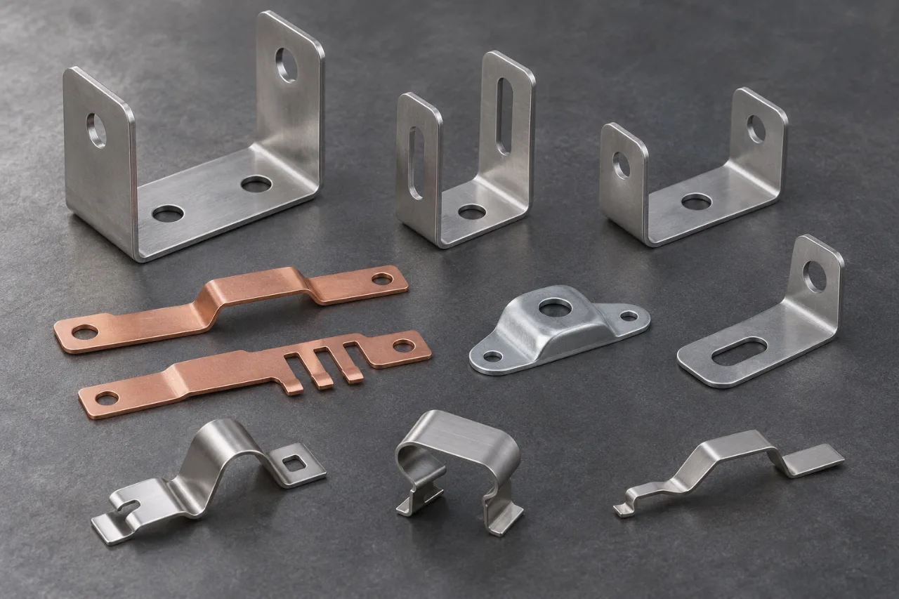
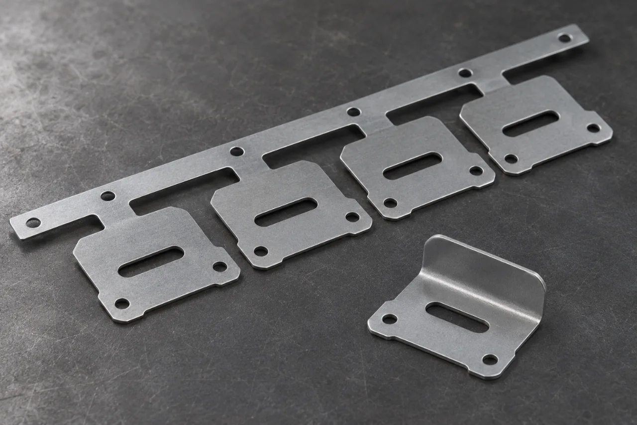
Electrical assemblies / contact interfaces
A Copper Electrical Contact Built Around Its Working Shape
A copper-alloy contact must meet its mating surface in the right position and condition. Its outline is only the starting point. This engineering case connects material temper, formed geometry, working deflection, contact finish and handling in one manufacturing brief. The aim is to define what the contact must do when installed, then make that function part of tooling, trial approval and repeat production. The review gives engineering and purchasing a shared basis for evaluating the complete component before repeat releases.
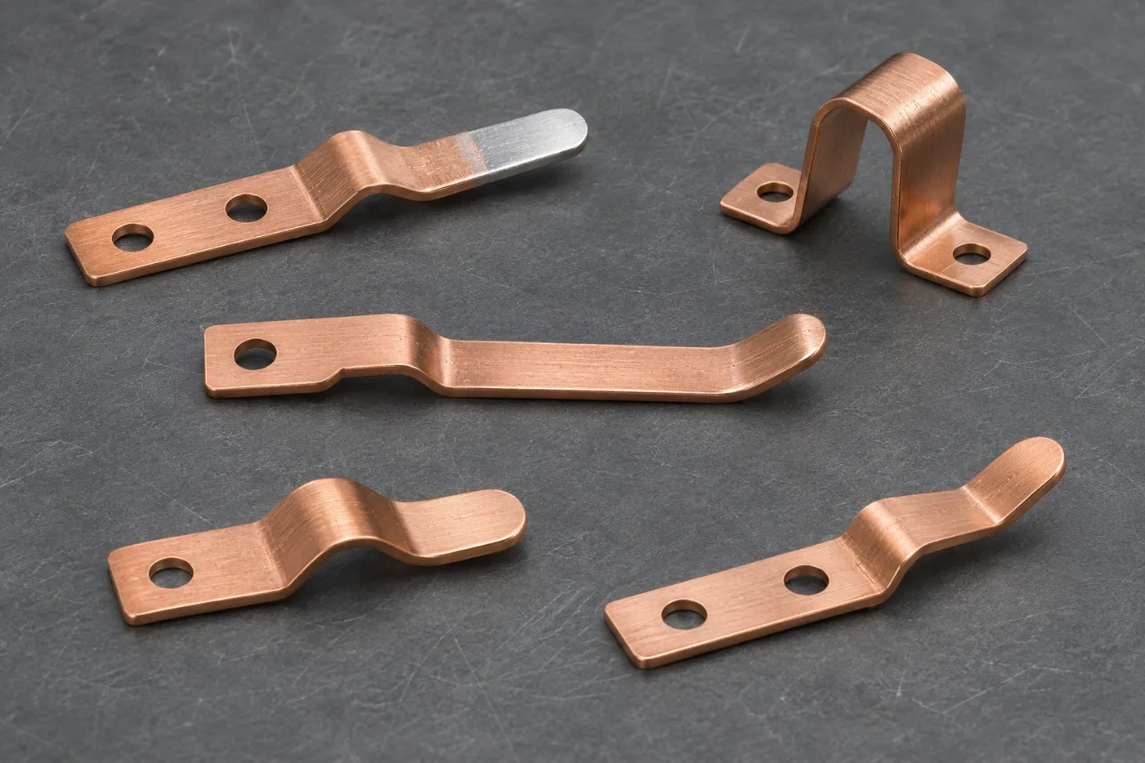
- Customer
- Electrical equipment OEM
- Component
- Formed copper-alloy contact with a defined mating surface
- Manufacturing route
- Strip stamping, controlled forming, edge preparation and specified plating
- Material
- Copper-alloy strip with an agreed temper and surface treatment
01 / The challenge
Make the requirement work in the real assembly.
A contact drawing needs to describe both the component on the bench and its behavior in the assembly. The same outline does not establish the installed contact position, working deflection or accepted surface. Those conditions must be defined before the die and sample plan can support a meaningful approval.
Purchasing also needs a complete material and finishing scope. Alloy, temper, plated surfaces, edge orientation and handling all form part of the supplied component. The project connects them to the functional requirement so engineering, the stamping review and receiving inspection assess one agreed contact specification.
- Component function
- Make contact at a defined position and working condition within an electrical assembly, using an identified locating and mating arrangement.
- Material and surface
- Connect copper-alloy grade, thickness, temper and forming behavior to the contact-face specification and the agreed finished condition.
- Approval method
- Check the controlled formed geometry alongside the specified installation, force or functional test, with an identified sample and test reference.
- Supply requirement
- Keep material, plating, edges, packing and the accepted revision together as the contact moves from sampling into recurring purchases.
02 / Engineering approach
Turn the difficult details into a manufacturing plan.
Define the contact in its installed state
The application is a formed copper-alloy strip component used to make an electrical connection within an assembly. It includes a mounting or locating feature, a formed section that establishes position, and a working surface that touches the mating component. The engineering brief begins with a section view of that interface. Show the installed position, the intended movement or deflection and the condition in which the contact is evaluated.
Distinguish the free-state shape from the working shape. A dimensioned outline can describe a part on the inspection bench without defining its installed behavior. Include the mating geometry and any specified force or functional test, with the test direction, fixture and acceptance condition. This gives the stamping review a direct connection between the drawing and the way the component is used, rather than leaving the most important requirement to interpretation.
Choose the alloy and temper as one specification
Specify the exact copper alloy, thickness and material condition. A general request for copper or brass does not establish the forming response or spring behavior of the finished component. Review those inputs alongside the bend radii, orientation and any grain-direction requirement. Where the product design requires both conductivity and elastic action, identify the material properties relevant to the application in the controlled procurement specification.
Keep proposed material alternatives within a defined approval process. Compare them against the same functional and forming requirements, and record the accepted condition before releasing the tooling baseline. If a treatment after forming is specified, include it in the manufacturing sequence and final acceptance state. The material order, tool trial and part inspection should all refer to the same requirement so a satisfactory sample can become a repeatable purchase.
Protect the working surface throughout the route
Mark the electrical contact face independently from cosmetic surfaces and general cut edges. Specify the plating system, areas to be treated and any areas to remain clear. Define the condition required after deburring, forming and finishing, including the dimensions that apply to the finished component. The aim is a surface specification that manufacturing and inspection can use, with enough detail to connect the coating to the mating interface.
Review burr orientation, part separation and forming access with that contact face in mind. State where edge preparation is required and where tool or handling marks are restricted by the drawing. Connect the finishing sequence to the part geometry and agreed contact requirements. If the part needs an assembly or electrical check, describe the supplied test method and the condition of the mating component rather than expecting a surface description alone to establish function.
Plan the die trial around shape and function
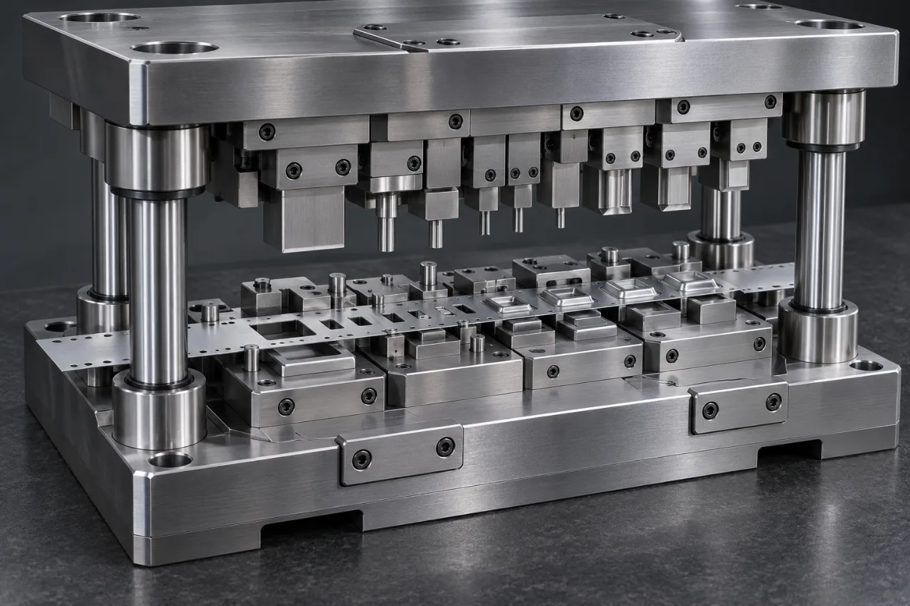
The die concept should explain how the strip is located, where the component is supported during forming and how it is separated from the carrier. Review the forming sequence around the important bends and the final working surface. Agree the material used for trials and the finish condition represented by each sample. This makes the purpose of the first sample clear and identifies any later sample needed to approve the completed route.
Connect the dimensional report to the functional check. The report records the agreed locating and formed features against the released drawing. The assembly or force check follows the agreed fixture, movement and test condition. Keep the sample identity and material condition with both results. A correction to meet the existing drawing can then be distinguished from a requested design change, with the next approval step stated in the project record.
Keep contact condition consistent from approval to receipt
An approved contact needs a stable repeat-order package. Keep the exact material, released geometry, surface specification, edge condition and test reference together. Identify any special characteristics and the agreed inspection frequency in the order. Where a change affects alloy, temper, formed shape or plating, review the affected checks before the revised part is released. This gives purchasing a clear record of what remains approved and what needs a new decision.
Packing should preserve the finished geometry and working surface. Review whether the formed features can nest, whether contact between parts marks the plated area and whether the receiving team needs a defined orientation or separated lots. State the labels and records required with the shipment. The delivery scope can then support a contact that is identifiable and ready for the receiving checks, rather than leaving its final presentation outside the quotation.
03 / Production route
From the first drawing to the next release.
- 01
Describe the working condition
Provide the mating section, installed position and specified contact or force requirement. Connect free-state dimensions to the condition used for functional approval.
- 02
Release material and surface requirements
Identify the copper alloy, thickness, temper, contact face, plating and edge direction. Review these inputs together with the forming sequence and separation point.
- 03
Trial and verify
Inspect the locating and formed features, then use the agreed fixture or functional check. Keep sample identity, material condition and final finish with the approval results.
- 04
Prepare repeat supply
Reference the accepted geometry, surface specification and test method in each release. Use packing that preserves the formed features and contact condition.
04 / Quality & acceptance
Give engineering and receiving the same reference.
| Control point | What defines approval |
|---|---|
| Working geometry | Contact position and formed profile evaluated in the agreed free or installed state. |
| Material identity | Specified alloy, thickness and temper linked to the order and trial material. |
| Functional surface | Plating, edge direction and contact-face requirements checked in the final specified condition. |
| Approval reference | Sample identity and drawing revision connected to the agreed dimensional and functional results. |
05 / Results & repeat supply
Connect the engineering work to purchasing value.
Manufacturing performance benchmarks for sampling, production and final acceptance.
- Sample turnaround
- 3–7 days
- Standard sample turnaround
- First-pass inspection
- 99.7–99.9%
- First-pass inspection acceptance range
- Batch defect rate
- 0.1–0.25%
- Batch defect-rate baseline
- Drawing conformity
- 100%
- Drawing-dimension conformity at final acceptance
The production baseline pairs a 99.7–99.9% first-pass inspection range with a 0.1–0.25% batch defect-rate range and 100% drawing-dimension conformity. For the contact procurement plan, keep the material condition, finished geometry and specified functional checks connected to the approved revision so those measures refer to a clearly defined component.
Standard samples follow a 3–7 day turnaround, with approved repeat production in a 12–20 day window. The first approved order develops into long-term batch reorders. The handover from sampling to repeat supply retains the contact-face requirements, agreed material and packing presentation rather than reopening the part definition at every purchase release.
The buying objective is a contact specification that connects material, shape and surface to an agreed working condition. That gives engineering a useful approval plan and gives purchasing a common basis for comparing complete supply proposals. Send the mating section and functional requirement with the drawing so the discussion reaches the interface early.
The quotation should separate tool development, sample approval, recurring stamping, finishing and any requested inspection records. That makes a contact with its required plating and functional acceptance comparable to another complete supply proposal. Include the test reference and mating section early so the technical discussion reaches the conditions that determine approval.
Customer feedback
Customer feedback highlights stable tolerances, fast responses and help resolving previous supplier quality and delivery problems. The value for a contact buyer is a clear conversation about the working interface, followed by an approved material, geometry and finish baseline that supports continued repeat production.
06 / Project questions
Before you quote a similar component.
Does an acceptable outline establish spring-contact performance?
The outline describes geometry, while working behavior also depends on material condition, installed position and deflection. Define the functional requirement and test condition with the drawing. The approval plan can then address the features relevant to the way the part makes contact.
What should be reviewed before changing the plating or temper?
Identify the proposed material or surface change against the approved baseline and review the affected dimensions, forming behavior and functional check. State what sample or report is required to release the revised specification. Keep the new requirement tied to a controlled part revision.
Why specify the exact copper alloy rather than only copper?
The alloy and condition form part of the material requirement for conductivity, forming and spring action. Identify the accepted grade, thickness and temper with the drawing. Any alternative can then be reviewed against the same application and approval requirements before the supply baseline changes.
How should finished contacts be packed?
Define the protection needed for formed features and plated contact faces, together with orientation, lot identification and receiving requirements. Review whether parts can nest or touch one another in transit. Include that presentation in the supply scope so packing preserves the approved component condition.
07 / Your project
Let the mating interface lead the review.
Send the formed contact drawing, copper-alloy specification and mating section. Include the working condition, surface requirements and approval checks needed for your next release.
- Part drawing, formed model and mating section at the current revision
- Copper-alloy grade, thickness, temper and defined grain direction
- Free-state geometry, installed position and working deflection
- Contact-face plating, edge direction and final surface requirements
- Agreed functional test, sample plan, release quantities and packing