Electronic modules / stamped protective hardware
Stamped Protective Cover for Electronic Modules
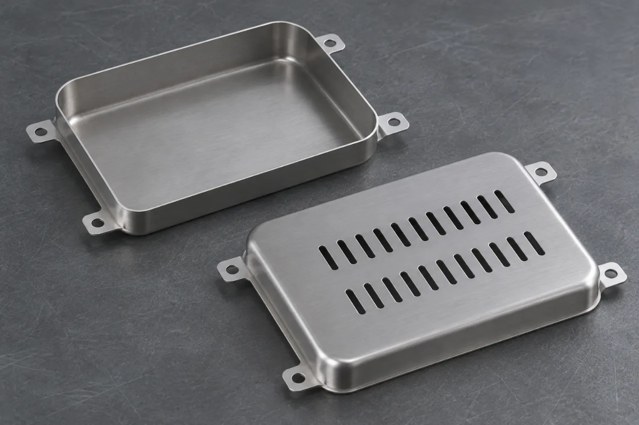
A protective cover has to arrive with the shape, edges, mounting features, and appearance the module assembly needs. This project follows a stamped cover from its mounting datums through forming, surface finishing, inspection, and packing. The aim is a complete specification for the finished component. Separate tooling from recurring part work, identify the appearance reference, and connect the sample plan with the module interface. Put the cover your equipment team intends to install at the center of the purchasing decision.
- Customer
- Electronic module and equipment OEM
- Component
- Formed stamped protective cover
- Manufacturing route
- Blanking, piercing, forming, edge preparation, finishing, and assembly checking
- Material
- Drawing-defined steel, stainless steel, or aluminum sheet
01 / The challenge
Make the requirement work in the real assembly.
The application is a formed sheet metal cover that mounts over an electronic module and becomes part of a larger equipment assembly. Its outer shape communicates only part of the requirement. The mounting pattern, flange relationship, clearances, accessible edges, and visible surfaces determine how the cover is installed and received. Include an assembly view with the individual drawing so the review can follow those relationships.
State which face establishes the mounting plane and which features locate the cover. Identify fixed interfaces, clearance openings, attachment details, and the areas your team touches during assembly or service. The supplier review can then focus forming and inspection around the module interface while keeping the visible surfaces and finished edge condition in the same scope.
- Application
- A formed sheet metal cover mounts over an electronic module within an equipment assembly.
- Main requirement
- Keep the mounting pattern, formed envelope, access clearances, finished edges, and visible faces aligned with the module interface.
- Supply scope
- Stamped and finished covers with the required secondary work, appearance checks, protective packing, and separately identified tooling.
- Approval reference
- A controlled formed drawing, assembly view, material specification, final finish reference, and identified sample inspection.
02 / Engineering approach
Turn the difficult details into a manufacturing plan.
Use the drawing to separate function and appearance
Mark the dimensions that control mounting and clearance rather than applying the same close requirement to every surface. Show the final formed condition and any restraint used during inspection. The mounting hole pattern, flange height, and relative position of access features need a shared datum reference. If the cover sits against another panel or sealing feature, include that mating arrangement with the project information.
Identify cosmetic faces explicitly. A visible upper surface, a hidden internal wall, and a flange under a fastener can have different acceptance requirements. Provide the finish designation and an approved reference for color, texture, or permitted marks. This gives purchasing a complete specification and gives sample review a defined basis for appearance approval.
Select stock around forming and finished use
Specify the material standard, grade, thickness, condition, and any surface coating on the starting stock. Review the choice against the cover depth, corner geometry, mounting flange, and the planned finish. Keep grain direction and material condition visible where they affect the forming review. The material in the trial plan should represent the production stock identified for the finished cover.
If material or finish options remain open, describe the mechanical use, appearance priority, and assembly environment. Compare options as complete routes that include forming, edge preparation, treatment, inspection, and packing. Avoid hiding a finish change inside a base-material comparison. Separate quotation options let your team evaluate cost against the delivered component it intends to approve.
Plan the cut and formed features as one route
Review blanking, piercing, forming, trimming, and any secondary operation together. A hole or opening that is convenient in the flat blank still needs to land in the correct relationship after forming. Establish how the part is located through the sequence and which surfaces carry the mounting references. Discuss the final cutoff or trim condition when it affects the exposed edge.
Compare staged tooling and progressive tooling against the design's maturity, expected order pattern, material use, and number of required operations. Separate one-time tooling from recurring component prices. Keep any dedicated fixtures, trial samples, finishing, and inspection records visible in the proposal so the purchasing comparison follows the complete scope.
Make edge quality part of assembly readiness
Call out the edges that are handled, the openings near wiring or mating components, and the permitted burr direction. Define the finished edge requirement and include any secondary edge preparation in the quote. Review the location of trim witnesses and handling features against the way the cover is installed. This directs the manufacturing discussion toward the edges that matter to the assembly.
Add access requirements for fastening and service. A screw may fit through its opening while a driver needs a different working envelope. Include the fastener specification, assembly sequence, and relevant access model when those details control the design. The cover review then addresses the operation your team performs with the component rather than only checking the part in isolation.
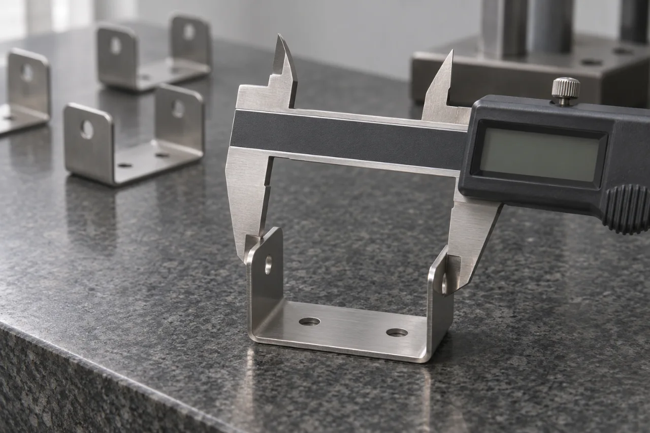
Approve appearance in the finished condition
The sample plan should identify the final surface treatment, visible faces, acceptable marks, and viewing reference requested by the buyer. Coordinate these items with handling and packaging. If threads, mounting contacts, or fitted surfaces need masking, show them on the drawing and include them in the finishing scope. Evaluate the approved cover in the state that will be delivered.
Connect the cosmetic reference with dimensional inspection and assembly fit. Treatment can be part of the functional interface as well as the appearance. State which dimensions apply after finishing and how the mounting features are checked. A common sample identity lets the approval record show geometry, edge condition, finish, and fit for the same set of parts.
03 / Production route
From the first drawing to the next release.
- 01
Map the mounting relationship
Review the cover and module together. Identify mounting datums, clearance openings, fasteners, assembly access, visible faces, and handled edges. Align the model, drawing, and bill of materials to one part revision.
- 02
Develop the complete stamping route
Plan blanking, piercing, forming, trimming, and secondary preparation around the final mounting geometry. Compare tooling routes against design stability and repeat demand, with material, final cutoff, and burr orientation in view.
- 03
Approve the finished sample
Check geometry, assembly fit, access, edge condition, and appearance in the specified final state. Use the agreed viewing reference and measurement setup and connect all findings to the same sample identity.
- 04
Prepare recurring deliveries
Release the accepted drawing and finish reference with the packing and receiving instructions. Keep tooling identity and any approved revision connected to recurring part quantities, inspection records, and shipment labels.
04 / Quality & acceptance
Give engineering and receiving the same reference.
| Control point | What defines approval |
|---|---|
| Mounting datums and cover envelope | Check the mounting pattern, flange relationship, access openings, and overall formed definition from the specified datums. Include the defined restraint or assembly check where it establishes the delivered fit. |
| Edges and assembly access | Inspect the drawing-defined edge condition and burr direction on handled and functional openings. Confirm the specified fastener interface and the access required to assemble and service the cover. |
| Appearance and final finish | Use the approved visible-face and finish reference. Confirm treatment, color or texture where specified, masking, and accepted marks in the same final condition used for dimensional and assembly approval. |
| Identity and surface protection | Match part number, revision, quantity, material and finish records, and inspection references. Separate visible surfaces and formed features in the agreed packing so the receiving team can identify and use the approved component. |
05 / Results & repeat supply
Connect the engineering work to purchasing value.
Manufacturing performance benchmarks for sampling, production and final acceptance.
- Sample turnaround
- 3–7 days
- Standard sample turnaround
- Batch production
- 12–20 days
- Repeat production window
- Final dimensions
- 100%
- Drawing-dimensional conformity at final acceptance
- Batch defect range
- 0.1–0.25%
- Shared batch quality baseline
The standard program baseline sets samples at 3–7 days and repeat batch production at 12–20 days, with a shared 25–40% lead-time improvement range. For the protective cover, the approval sequence connects the mounting geometry, access openings, finished edge condition, appearance reference, and packaging so the sample becomes a complete production and receiving baseline.
Commercial and production planning uses the shared 15–30% comprehensive cost-reduction and 35%+ assembly-efficiency baselines. The quality reference combines 99.7–99.9% first-pass inspection, a 0.1–0.25% batch defect range, and 100% conformity to the drawing dimensions at final acceptance. The first-order-to-long-term-repeat-supply model keeps those controls tied to the accepted cover revision and finish.
Purchasing a cover as a finished component keeps the important costs visible. The comparison includes tooling, trial work, stamped geometry, edge preparation, finishing, appearance approval, inspection, and packing. The equipment team can evaluate the mounting relationship while the buyer sees the complete delivered scope. A lower base price becomes easier to assess when the operations behind it are explicit.
The approval reference supports first-order development and long-term repeat batches. Keep the accepted formed drawing, material, finish, visible-face reference, edge requirement, and packing method together. This gives engineering, quality, and receiving the same component definition and keeps later discussions about release quantity or delivery timing connected to the part that has been approved.
Customer feedback
The feedback summary brings together stable mounting tolerances, prompt responses on drawing and finish questions, and an organized response to previous supply concerns around yield and timing. The cover review links those priorities to clean edges, consistent appearance, a usable sample record, and protection of the accepted surfaces during delivery.
06 / Project questions
Before you quote a similar component.
Should the RFQ include the module assembly?
Include an assembly or mating view alongside the cover drawing. It explains the mounting plane, locating features, internal clearances, fastening access, and service envelope. Keep the part number and revision aligned across the files so tooling, sample inspection, and the purchasing scope refer to the same component.
How do we specify the cosmetic surfaces?
Mark the visible faces and provide the required finish designation and appearance reference. Identify accepted marks and the viewing method used for approval. Coordinate that reference with handling and separated packing, and distinguish visible external surfaces from hidden faces and functional mounting interfaces.
Which dimensions should be inspected after finishing?
Identify the dimensions that define the finished mounting and mating relationship and state their acceptance stage. Include masking for fits, contacts, or threads where specified. The sample record should identify its final condition so geometric checks, appearance approval, and assembly findings can be read together.
What should a complete cover quotation include?
Separate tooling and trial work from recurring material, stamping, forming, edge preparation, finishing, inspection, and packing. Include supplied hardware or secondary work where required and state the delivery basis. Use the same finished scope when asking for different order quantities.
07 / Your project
Put mounting fit, finish, and edges into one cover brief.
Send the cover drawing and module view, mark the critical mounting features and visible faces, and include the material, quantities, and required finish. Start the review with the finished component your team needs to assemble.
- Formed cover drawing and CAD with the module assembly or mating view
- Material grade, thickness, condition, finish, and any required records
- Critical mounting pattern, cover clearances, fasteners, and assembly access
- Visible faces, appearance reference, burr direction, and finished edge requirement
- First and repeat quantities, packing instructions, ship-to destination, and approval milestone