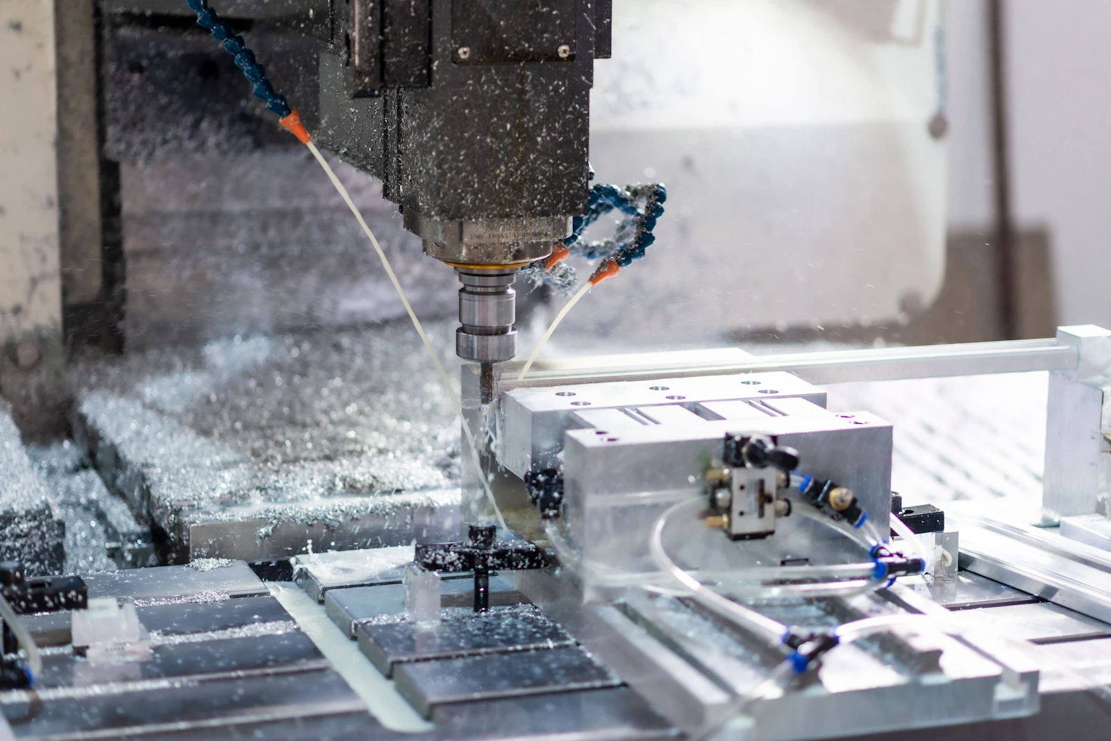
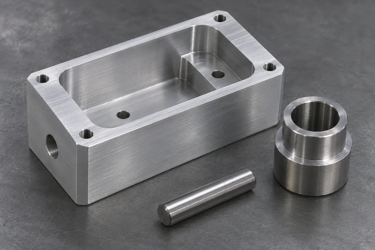
CNC machining supports WenXinDa projects with prototypes, related metal components, and secondary features alongside our main stamping and die tooling work. Milling and turning can produce housings, plates, shafts, or specific mating surfaces where the drawing calls for them. Send the geometry, material, quantity, and finished-part requirements so we can review the scope.
Milling creates pockets, faces and hole patterns; turning creates diameters, bores and shoulders. Combining the two gives a part its functional interfaces while keeping the critical features connected to a clear datum.
Start with the part function, then choose the operations that create its working features.
CNC machining
Made around the mating features
Locating holes, sealing faces, threads and bearing fits guide the machining plan, so precision is applied where your assembly needs it.
Material through to finish
Alloy, stock condition, coating and inspection are considered together, including the dimensions that must hold after finishing.
Prototype to repeat order
Plan the first sample and later batches on one clear specification, with revision changes and delivery needs visible from the start.
01 Scope
Practical manufacturing support for your parts
A good part brings together the right material, an efficient manufacturing route and a finish that suits its working environment. These are the details we connect during project review.
01
Choose the metal for the job
Balance strength, weight, corrosion resistance and machinability. A well-chosen grade can meet the application without adding avoidable cutting or finishing cost.
02
Functional surfaces, carefully planned
For heat spreaders, electrical contacts and sealing parts, the working surface matters as much as the overall shape. Show those interfaces in the drawing.
03
Finishing allowances
Coating is part of the dimension plan. We look at bores, threads and contact faces early so masking and final inspection protect the intended fit.
04
Prototype and production quantities
A small first batch can validate fit; repeat demand can justify more efficient fixtures or stock preparation. Share both quantities to compare the options.
05
Machining to support formed parts
A stamped or fabricated blank may need a thread, bore, or mating face machined afterward. Agree datum transfer, process sequence, and the finished inspection condition so those interfaces remain connected to the formed geometry.
06
Inspection deliverables
Link the drawing revision to critical measurements and material records. The inspection package then supports your receiving checks and assembly release.
Choose milling, turning, or a combined route
The starting shape and the surfaces that control assembly usually point to the first operation. A housing with pockets and mounting faces calls for milling; a shaft with concentric diameters calls for turning. Parts with both feature families may use more than one setup or process.
Route
Good starting point
Discuss before quoting
CNC milling
Prismatic brackets, plates, housings, pockets, and mounting faces
Tool access, internal corner radii, datum faces, and how the part is held between setups
CNC turning
Shafts, sleeves, bushings, spacers, and other rotational parts
Concentric features, slender sections, cross-holes, and the relationship between diameters
Milling plus turning
Rotational parts with flats, off-axis holes, or mounting features
Which operation establishes the primary datum and where a second setup can change alignment
Machining after fabrication
Weldments or formed blanks with a small number of critical interfaces
Whether final machining should follow welding or forming to control distortion
The drawing and production quantity determine the final route; a part name alone is not a process specification.
For an early prototype, CNC can preserve design flexibility while mating features are still changing. For recurring orders, the same geometry may benefit from a different blank, fixture, or combined route. Send both the immediate order and the expected repeat quantity so those options can be compared on the same specification.
Aluminum grades for machined and formed parts
6061 is a practical starting point for many machined brackets and housings. Higher strength, a formed shape or a particular corrosion environment may lead to another alloy. Use the table to narrow the choice before specifying the temper and finish.
Grade
Typical use
Notes
6061-T6
General structure, brackets, weldments
Versatile; anodize friendly
7075-T6
High-strength structural components
Review corrosion environment and finishing
5052-H32
Formed sheet parts and panels
Discuss sheet fabrication when bending is required
2024
Strength-focused components where specified
Confirm temper and corrosion protection
Include the material standard and certificate requirement with the grade so the stock and records match your purchasing specification.
For steel and stainless steel, specify the full grade and supply condition. Hardened stock, thin sections, and corrosion requirements affect tool selection, workholding, and finishing. Material substitution should be agreed before the order is placed.
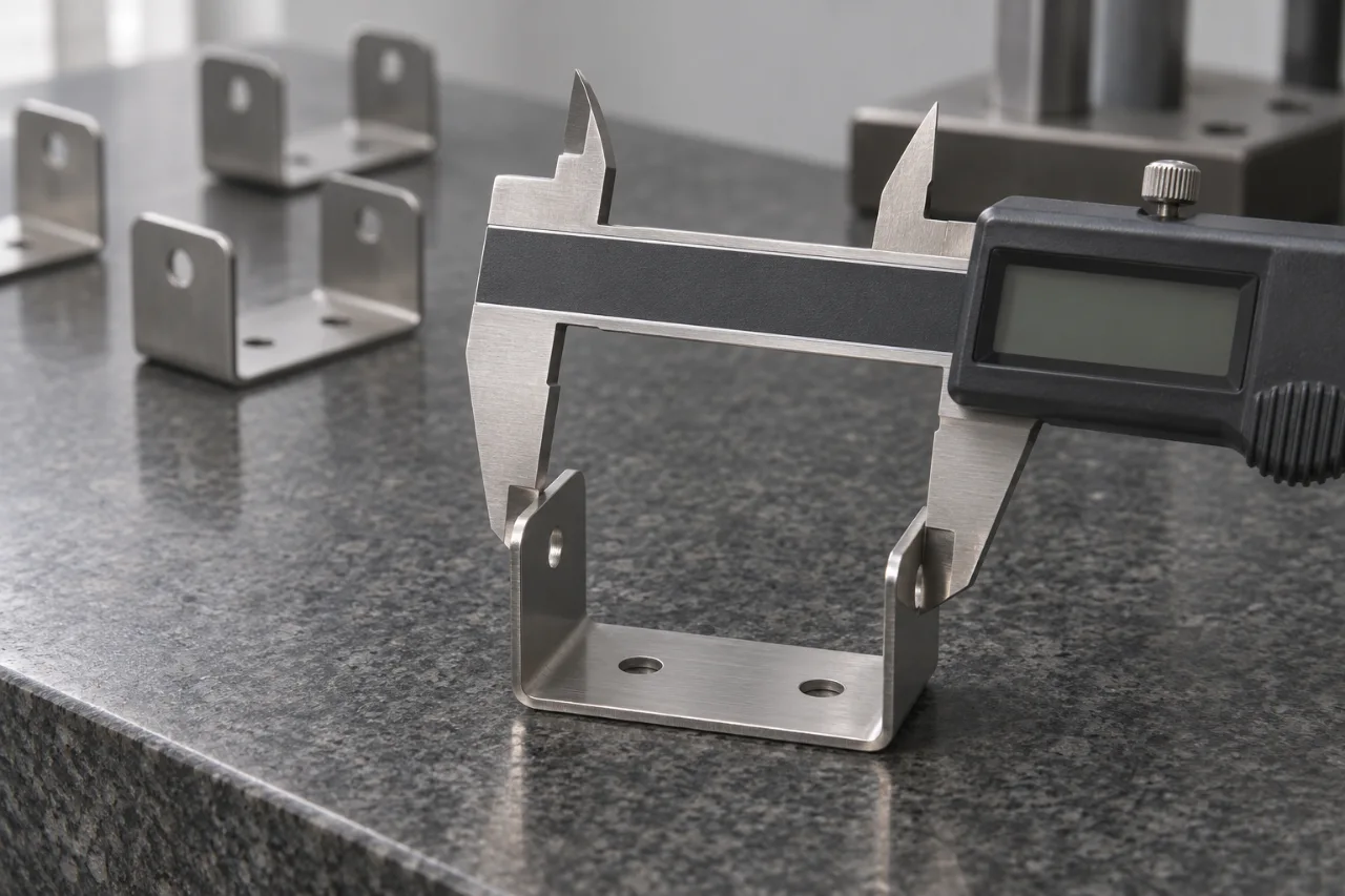
Checking a formed feature against the part specification
Material choices beyond aluminum
Choose the metal around the part function. Steel brings strength and wear options, stainless steel supports corrosion-sensitive applications, and copper alloys serve thermal or electrical interfaces. Each choice also affects cutting effort and finish.
Material family
Typical reason to consider it
Question for the RFQ
Carbon or alloy steel
Strength, wear, or a specified heat-treatment route
What condition is required at final inspection, and which surfaces need corrosion protection?
Stainless steel
Corrosion resistance or a cleanable exposed surface
Which grade and finish are specified, and are welds or passivated surfaces involved?
Brass or copper alloy
Electrical, thermal, or contact properties
Which alloy, conductivity requirement, and plating or contact areas matter?
Aluminum alloy
Lower mass, thermal management, or anodized appearance
Which temper, cosmetic faces, and post-finish dimensions must be controlled?
A complete alloy and condition make quotes easier to compare and help keep repeat orders consistent.
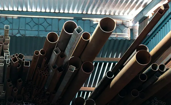
Bar, plate and prepared blanks each offer a different balance of material yield and machining effort.Process detail
Define the features that control fit
Good tolerance planning starts with the assembly. Control the features that locate, seal or move, and give noncritical surfaces enough freedom for an efficient machining route.
Feature
Specify on the drawing
Review during quoting
Linear dimension
Nominal size, limits, and datum references
Material stability and setup access
Hole diameter
Size limits, depth, and fit requirement
Machining route and inspection access
Flatness and position
Controlled surface or feature and datum scheme
Clamping condition and measurement method
Measure mating features in their final condition, with the same datum references used by the assembly.
Custom CNC parts for everyday engineering problems
CNC is useful when a component needs accurate interfaces, machined pockets or several features in one solid body. These common part types show how geometry connects to the manufacturing route.
Part type
Why CNC fits
What to send
Mounting bracket with slotted holes
Machined faces, slots, and threaded features.
STEP plus PDF with thread callouts
Machined housing or cover
Pockets, mating faces, and sealing interfaces.
STEP plus sealing-face and finish notes
Shaft, spacer, or bushing
Rotational features suited to turning.
PDF with diameter and runout limits
Tooling plate or fixture base
Flatness and hole position are the whole job, and both are measurable.
STEP plus datum scheme
For a thin cover or a repeated clip, compare sheet metal and stamping alongside CNC before choosing the route.
When to compare other processes
A thin enclosure may suit sheet metal fabrication, while a repeated clip shape may justify stamping tooling. Compare the complete route: material use, setup, tooling, secondary operations, inspection, and expected repeat quantity. For a mixed-process part, identify which surfaces establish the datum for the next operation.
Design details that change machining effort
A model can be technically machinable while requiring extra tools or setups. Mark functional features first, then review the geometry around them for a simpler route.
Feature
Why it matters
Useful design decision
Deep narrow pocket
Long tools reach less rigidly and can increase cutting time.
Confirm whether full depth is functional; allow a larger corner radius where the assembly permits.
Thin wall or floor
The part can move under clamping or cutting forces.
Identify the load case and cosmetic faces; review added support or a different stock form.
Small internal corner
A rotating cutter leaves a radius in internal corners.
Specify only the corners that must clear a mating feature; use relief where appropriate.
Cross-hole or side feature
May require another orientation, fixture, or operation.
Show the feature relationship to the main datums and ask whether its position is critical.
Threaded blind hole
Thread engagement and bottom clearance depend on depth and tool access.
Call out thread standard, required usable depth, and whether an insert is acceptable.
Proposed DFM changes need drawing approval; functional requirements take priority over a simpler cut.
Inspect the features that matter after finishing
Inspection should follow the same datum scheme used by the assembly. Decide which dimensions are checked before coating, which are checked after coating, and what records need to accompany the parts.
Requirement
Information to provide
What the review resolves
Mating bore or shaft
Fit, location, datum, surface condition, and final state
Machining and measurement sequence, including any coating allowance
Sealing face
Flatness or finish requirement and the matching seal
Protection during handling and method of checking the face
Thread and insert
Thread callout, engagement, gauge requirement, and installation state
Whether the thread is machined, protected, or inspected after finishing
Visible surface
View side, appearance sample or written acceptance criteria
Where tool marks are acceptable and how parts are packed to protect the finish
Identify inspection records at quotation; a visual check, dimensional report, and first-article package are different deliverables.
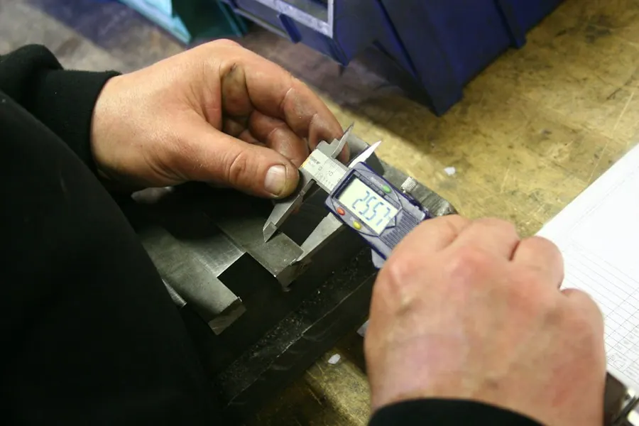
Inspection connects the measured feature to the datum and fit requirement on the drawing.Process detail
A better CNC quotation package
Send a STEP model for geometry and a controlled PDF drawing for what must be accepted. The drawing should identify units, revision, material condition, threads, datum references, finish, and critical dimensions. Add target quantity, repeat demand, delivery destination, and requested documentation in the enquiry.
If an existing part is being resourced, include the current drawing revision and explain any known assembly issue. A photo can help communicate function, but it does not replace a dimensioned drawing. When multiple parts form an assembly, include the mating context so the proposed process can be reviewed around the complete fit rather than each part in isolation.
From first prototype to a controlled repeat order
The information needed changes as the design matures. A prototype may answer a fit question; a repeat order needs a stable revision, agreed inspection scope, and a consistent finish. Share where the part sits in that journey so the quote can address the right decision.
Project stage
Decision to make
Useful information to send
Early design sample
Can the shape be made and assembled as intended?
Current model, the features being tested, permitted material alternatives, and an expected revision window.
Functional prototype
Do the material, finish, interfaces, and load path work together?
Controlled drawing, mating-part context, critical dimensions, finish state, and test or inspection needs.
Pilot build
Is the process repeatable enough for the planned assembly?
Approved revision, batch quantity, sampling or report scope, packaging, and any change-control process.
Repeat production
Can each release use the same accepted specification?
Forecast, release schedule, approved material and finish, drawing history, and required shipment documents.
A new revision can change the manufacturing or inspection route; quote each revision against its own requirements.
Compare quotes on the complete manufactured part
Two quotes for the same CAD model may include very different deliverables. Ask each supplier to identify the material condition, process assumptions, finishing scope, inspection records, and packing method before comparing price or schedule.
Cost driver
Why it changes the quote
What to decide
Starting stock
Bar, plate, or a prepared blank changes material yield and first setup.
Whether an alternate stock form preserves the required material condition and part function.
Setup count
Features on several sides require reorientation and may need a dedicated fixture.
Which feature relationships truly need a common setup or tight datum control.
Cycle time
Deep pockets, complex contours, difficult access, and heavy stock removal take longer.
Whether nonfunctional geometry can change without affecting assembly or appearance.
Finish and protection
Masking, coating, appearance inspection, and individual packing add operations.
Which surfaces are functional, visible, or protected during shipment.
Documentation
A material certificate or detailed dimensional report has a different scope from routine part checking.
Which records are needed for approval and which must accompany each release.
Specify the comparison basis so a lower unit price does not hide an omitted operation.
Three assembly questions that clarify the drawing
A housing, bracket, or shaft is accepted in the context of what it mates with. The same nominal geometry can need different tolerances and finishes depending on its function. Use the questions below when a drawing does not yet mark every critical feature.
Assembly question
Example decision
Drawing consequence
What locates the part?
A dowel hole may locate a bracket while a slotted hole only permits adjustment.
Dimension and inspect the locating hole from the assembly datums; avoid applying the same limit to every hole by habit.
What surface transfers load or seals?
A motor mount face and a gasket face perform different functions.
Identify the contact area, required finish, flatness or position, and any coating exclusion.
What can be seen or handled?
An internal tool mark may be acceptable while an exposed edge or cover face is not.
Mark cosmetic faces, deburring expectations, and the packing needed to protect them.
The goal is to put control where it protects function, rather than applying a blanket tolerance to the whole part.
Turn the assembly requirement into a machining plan
A CNC quote becomes more useful when the functional interfaces are clear. A locating bore, gasket face or mounting pattern may deserve specific control while surrounding features can use the agreed general drawing requirements. Show us what the part connects to and which relationship governs assembly. The review can then connect stock choice, workholding, machining sequence and inspection around the features that protect function.
Machined part brief
Route to review
Finished-part approval
Aluminum housing with a cover and connector opening
Compare stock size, pocket depth, corner radii and access to the opposite face. Identify the cover interface before choosing the finish and masking.
Check the locating and cover interfaces in the specified final condition, including threads and any coating exclusions.
Turned sleeve with a bore and locating shoulder
Review the main axis, wall thickness, bore access and the shoulder that sets axial position. Connect later flats or cross-holes to the same datum strategy.
Inspect the functional diameters, relevant geometric relationship and shoulder position using the released drawing.
Machined features on a stamped or fabricated blank
Provide the starting-blank and finished drawings together. Define the location and allowance for the faces, bores or threads machined after forming.
Approve the complete component, with the machined interface checked relative to the finished assembly datums.
Make your next quote easier to act on
Send the controlled model and drawing together with the alloy, condition, finish and order quantity. Include the target date, destination and inspection records required for acceptance. If you want a cost review, identify the features your design team can consider changing. A discussion around blank size, tool access, setup count and feature-specific control is more productive than applying the same cost target to every surface.
For a repeat order, reference the approved sample and drawing revision, then list any change separately. A material substitution, new finish or altered mating component can affect the accepted interface even when the main model looks familiar. Keeping the revision, finished condition and inspection scope connected gives purchasing and engineering the same basis for the release.
Have a difficult fit or a recurring assembly issue? Include a short note with the drawing so we can focus the machining and inspection review on the problem you need to solve.
Application brief
Use the application, mating features and approval checks to turn a drawing into a clear manufacturing brief. Bring your part number and the assembly requirement that drives the design.
Milled and turned features for assembly interfaces
Tooling & equipment / supporting CNC parts
CNC Locating Interface
A machined locating block, fixture component or mounting interface often carries the dimensions that connect several parts. A tight tolerance has value when it protects the intended fit. The review starts with the locating scheme, access for machining and the final inspection condition, connecting the part drawing to the assembly task.
Engineering & inspection +
The objective is a supporting component with a clear fit requirement and a proportionate inspection plan. Mark the mating features when you request a quote so the review targets the dimensions that do the work.
Engineering approach
Review the model and drawing together. Establish the datum features, mating holes, threads and surfaces that control position or alignment.
Plan setups around tool reach, workholding and the relationship between critical features. Discuss corner radii and deep features that affect the machining route.
Include material condition, surface treatment, masking and deburring in the same plan. Define whether critical dimensions apply before or after treatment.
Approval checkpoints
Inspect the critical relationships from the specified datum system.
Check thread requirements, accessible edges and mating surfaces.
Link inspection records and part identification to the drawing revision.
Frames, sensor mounts, and wear plates for equipment that runs daily.
Electronics & power
Heat spreaders, bus bars, shields—pair material with finish for EMI or thermal goals.
Mobility suppliers
Brackets and adapters for EV and legacy programs at pilot through production volumes.
Test & instrumentation hardware
Fixtures and mechanics where traceability and inspection plans are agreed up front.
03 Finishing
Finishing & post-processing
Finishing protects the part and prepares it for use. Choose the treatment around corrosion, wear, appearance and contact surfaces, with masking and final dimensions planned from the start.
Option
What it does
Common use
Anodize (Type II/III)
Controlled oxide layer; color or clear; improves corrosion on aluminum.
Start with the files you have and highlight the features that matter most. These four details help us connect your design to the manufacturing route and finished-part price.
01
Current revision
Provide the dimensioned drawing and available CAD with matching part number, revision, and units.
02
Material & finish
State the complete material specification, condition, finish requirements, and any permitted alternatives.
03
Critical features
Identify functional dimensions, datum features, cosmetic criteria, and required inspection records.
04
Quantity & delivery
Include release quantity, expected repeat demand, destination, and the required delivery date.
Add the certificate type, material standard and traceability needs to the RFQ. This lets the stock purchase and inspection records follow the same specification as the finished part.
Can a project combine welding and machining?
Include weld symbols, critical faces, and inspection requirements so the sequence can be reviewed. Welding can affect dimensions, so final machining may need to follow assembly.
What files help most?
STEP/IGES for machined geometry; PDF drawing with finishes, threads, and inspection marks.
Should I choose CNC milling or turning?
Start with the part geometry: prismatic pockets and faces usually point to milling, while concentric diameters usually point to turning. A part with both may need a combined route. Send the model and drawing so access, workholding, and datums can be reviewed.
Can I quote from a 3D model without a 2D drawing?
A model communicates geometry, but it may not define material condition, tolerances, finish, threads, or inspection. A dimensioned PDF is useful for any feature that controls fit or acceptance. If it is not available, identify the missing requirements in the enquiry.
How do surface treatments affect a machined fit?
Some coatings add thickness or change the surface state. Mark the mating bores, threads, contact faces, and any masking areas, then specify whether dimensions apply before or after finishing. The coating and inspection sequence can be agreed during review.
What makes a CNC part more expensive?
Material form, removed volume, setup count, tool access, tight feature-specific tolerances, finishing, inspection records, and order quantity all influence a quote. A DFM review can identify which features drive cost without changing the required function.
Can I change the material or finish after approving a prototype?
A material or finish change can alter dimensions, corrosion performance, appearance, and inspection. Issue a new drawing revision and confirm whether another sample or report is needed before repeat production.
What should I compare between two CNC quotations?
Check the stock condition, included operations, finish, feature-specific inspection, documentation, packaging, and delivery basis. A quoted unit price is only comparable when both suppliers have interpreted the same drawing and acceptance scope.
Should all dimensions have the same tight tolerance?
Usually the assembly has a smaller set of locating, sealing, or moving features that need explicit control. Identify those on the drawing and state how they will be measured. Noncritical dimensions can follow an agreed general tolerance when appropriate.
Can you machine an existing welded or stamped blank?
Yes. Machining a formed or welded blank is useful when only selected bores, faces or threads need close control. Send the blank drawing and final drawing together, with the datums that connect the two stages.
How should cosmetic and functional surfaces be distinguished?
Mark visible faces, contact faces, and protected areas separately. A surface finish value alone may not describe acceptable tool marks or handling marks. A written appearance criterion or agreed sample helps make the inspection decision clearer.
Next step
Let us help you move the part forward
Send your drawing with the material, quantity and target delivery date. Tell us where the part fits and what matters most, whether that is assembly, appearance, cost or repeat supply.