
Skip to content

CNC machining / milling

CNC Milling for Custom Metal Parts

CNC milling produces custom metal parts with pockets, flat faces, slots and accurately positioned holes. WenXinDa supports milled housings, plates, brackets and fixtures for prototype builds and repeat orders. We focus the machining plan on the surfaces that locate, seal and fasten your assembly, then look for practical ways to reduce unnecessary setups and cutting time.

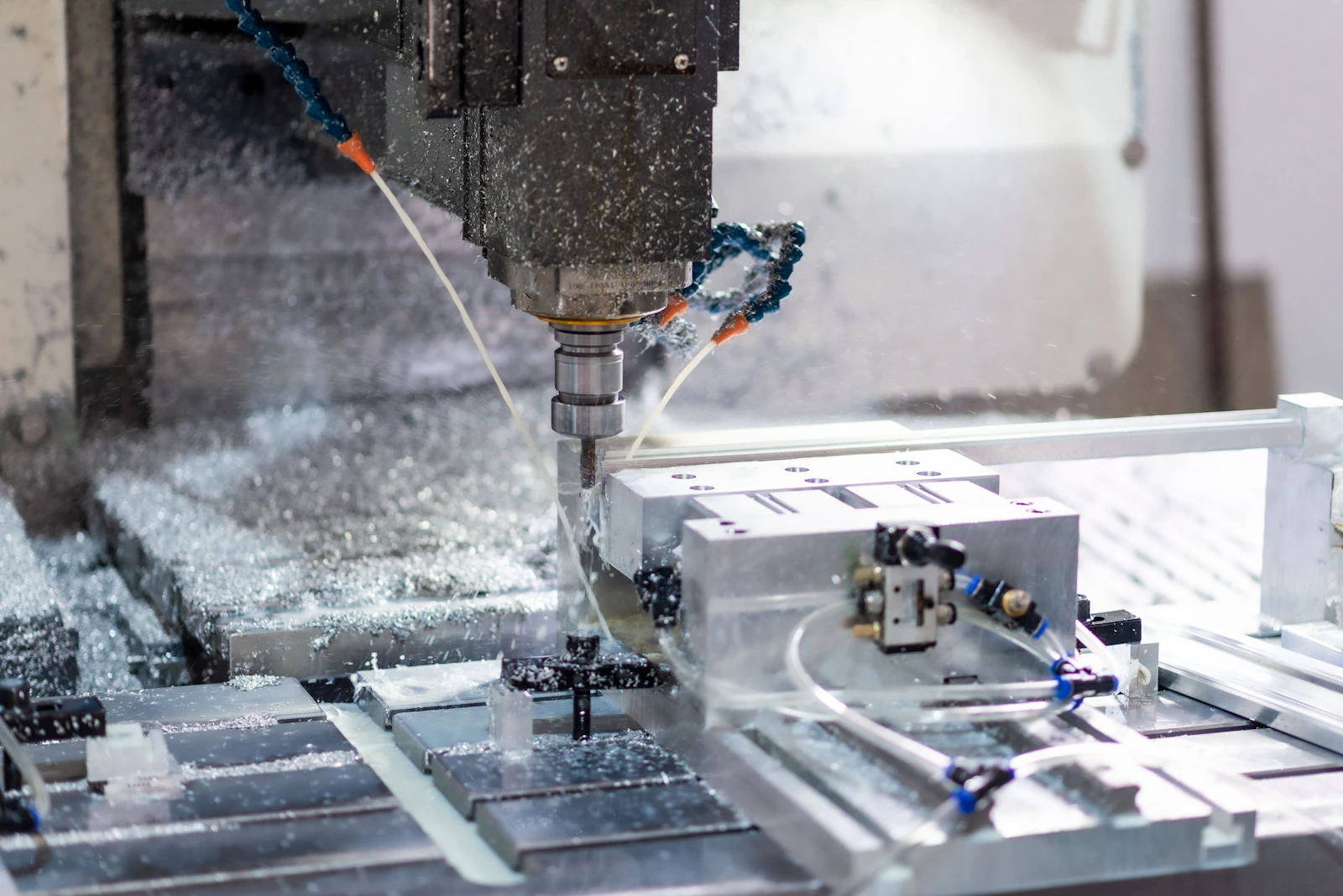
CNC milling cutter machining a metal workpiece
CNC milling in progress

Process at a glance

From stock to controlled interfaces

A milled part starts with stock and a plan for holding it securely. Roughing creates the main form; finishing controls the surfaces and features that matter to assembly. Additional setups may be needed to reach opposite faces, which makes datum strategy and access part of the cost discussion.

The operation creates the geometry; the part function determines which features need the closest control.

CNC machining A rotating cutter removes material from a fixed workpiece to form pockets and other features. CUTTERWORKPIECE01 / REMOVE
CNC machining

01 Fit

CNC milling for housings, plates and precision interfaces

Choose milling when several functional features need to work together in one solid part. It is especially useful for locating faces, pocketed bodies and hole patterns that must align with another component.

Housings and enclosures

Machined pockets, locating faces and threaded mounting points can be combined in a single part. Internal corners, cavity depth and wall thickness influence tool access.

Plates and brackets

Flat stock can carry accurate patterns, counterbores, slots and edge features. Milling is especially useful when bearing or mating faces need control after other operations.

Fixtures and interfaces

Parts that locate another component benefit from a clear datum scheme and identified inspection points. Geometry alone does not specify how a part should be measured.

Design review

Design the features that make the part work

An efficient milled part gives the cutter room to work and the fixture a stable place to hold. Keep the features that matter to fit, then simplify deep pockets, hidden corners and nonfunctional surfaces where the design allows.

  • For a gasket or sealing face, show the contact area and required surface condition independently from cosmetic surfaces.
  • Include the starting-blank drawing when machining follows stamping, bending, casting or welding.
  • Identify the assembly datums and dimension critical holes and faces from those datums.
  • Show whether deep pockets and narrow slots are essential; long tools can add deflection and machining time.
  • Specify internal corner radii that permit practical cutters rather than assuming a sharp inside corner.
  • List threads, inserts, deburring and edge breaks in the drawing or notes.
  • Mark cosmetic faces and any surfaces that must remain free of clamp marks.
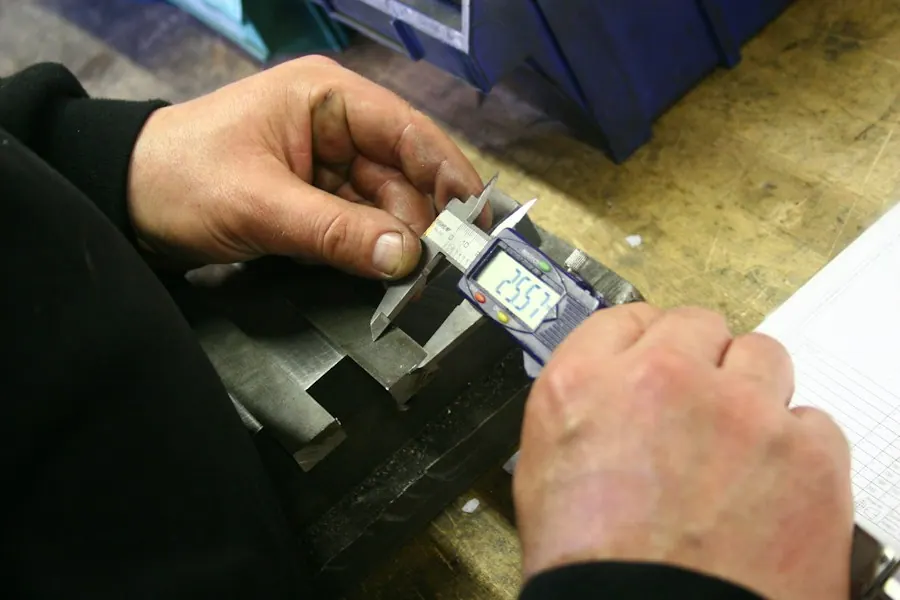
Digital caliper checking a feature on a metal component
Functional features need a defined measurement methodProcess detail

02 Decisions

The decisions behind a milling quotation

The most useful cost review starts with stock size, cutter access and the number of times the part must be repositioned. These decisions explain why two similar-looking parts can take very different amounts of machining.

DecisionWhat to specifyWhy it matters
Finishing stateDimensions before or after coating, masked bores and thread treatmentA fit is accepted in the condition delivered to assembly, so coating and inspection need the same dimensional baseline.
Starting blankSolid stock, pre-cut plate or a controlled formed or welded blankA near-shape blank can change machining time, workholding and the relationship between existing and machined features.
Stock formAlloy, temper and starting sizeBlank availability and the amount of material removed affect cost and timing.
Part accessPocket depth, undercuts, back-side featuresTool reach and the number of setups determine the machining route.
Functional dimensionsDatums, fits, threads and critical hole locationsThese drive toolpath planning and inspection.
Surface requirementsFinish, appearance faces and coating allowanceMachining and coating must be considered together at mating features.

03 Project route

How a milled part moves from drawing to order

The drawing, first part and final inspection should tell the same story. We work through the critical features before the order moves into repeat machining.

  1. 01

    Share design data

    Send a 3D model and a dimensioned 2D drawing, with material, finish and estimated demand.

  2. 02

    Review manufacture

    Resolve access, datums, threads and any ambiguous dimensions before the quotation is fixed.

  3. 03

    Approve the first part

    Agree which features, samples and records will be checked before repeat production.

  4. 04

    Release and ship

    Confirm identification, packing, destination and the documents needed at receipt.

04 Applications

Milled components for equipment and product assemblies

A housing needs a usable cavity; a fixture needs reliable location; a mounting plate needs its holes to line up. Each calls for precision in a different place.

Pocketed instrument housing

Project brief: an aluminum housing needs a cavity, connector access and a cover interface. Identify the sealing or seating face and the surfaces that locate internal components. Review pocket depth, corner radii, wall support and the features on opposite sides before fixing the machining route. The finished-part scope should include threads, deburring, coating exclusions and the inspection state. Send the cover or mating drawing so the quotation addresses the assembled housing.

Mounting plate with a locating pattern

Project brief: a plate connects a motor, sensor or fixture to an equipment frame. Separate locating holes from clearance holes and adjustment slots. Use the assembly datums to dimension the functional pattern, then review stock thickness, flatness and access for back-side features. The acceptance package can focus on the locating relationship and mating face while other dimensions follow the agreed general drawing requirements.

Machined interface on a formed blank

Project brief: only selected bores, pads or threads on a stamped or fabricated component require machining. Provide both the starting-blank and final-part drawings. Define the surfaces used for location after forming, together with the finished interface and inspection condition. A combined route can then be compared with machining the entire component from solid stock using the same finished-part requirement.

For a mixed part, combine processes around the function: turn the main diameter, mill the mounting features, or machine selected faces on a fabricated blank. A complete model makes those options easier to compare.

Application project brief

See the part.
Plan the details that matter.

Use the application, mating features and approval checks to turn a drawing into a clear manufacturing brief. Bring your part number and the assembly requirement that drives the design.

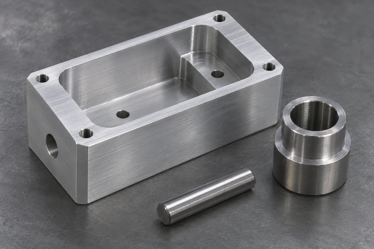
Machined aluminum housing, turned steel bushing and dowel pin
Milled and turned features for assembly interfaces

Tooling & equipment / supporting CNC parts

Keep mating features on the same page.

A machined locating block, fixture component or mounting interface often carries the dimensions that connect several parts. A tight tolerance has value when it protects the intended fit. The review starts with the locating scheme, access for machining and the final inspection condition, connecting the part drawing to the assembly task.

The objective is a supporting component with a clear fit requirement and a proportionate inspection plan. Mark the mating features when you request a quote so the review targets the dimensions that do the work.

Explore the project approach

Engineering approach

  • Review the model and drawing together. Establish the datum features, mating holes, threads and surfaces that control position or alignment.
  • Plan setups around tool reach, workholding and the relationship between critical features. Discuss corner radii and deep features that affect the machining route.
  • Include material condition, surface treatment, masking and deburring in the same plan. Define whether critical dimensions apply before or after treatment.

Approval checkpoints

  • Inspect the critical relationships from the specified datum system.
  • Check thread requirements, accessible edges and mating surfaces.
  • Link inspection records and part identification to the drawing revision.

05 Common questions

Questions before you request a quote

Straightforward answers to the design, manufacturing and purchasing questions that come up before an order.

Can milling be combined with a stamped or fabricated component?

Yes. Selected faces, bores and threads can be machined after forming or assembly. Provide the starting condition and final drawing together, with the locating datums that connect the operations. The review then covers workholding, machining allowance, finish and acceptance on the complete part.

What makes a first-part report useful?

Identify the feature numbers, datums, material and finish condition that matter to acceptance. Agree the report format and sample quantity before machining. Measurements should refer to the same drawing revision and the same finished condition that your receiving team will use.

What is CNC milling best suited for?

CNC milling is well suited to housings, brackets, plates and fixtures with pockets, flat faces and holes in several positions. It is a practical choice when several features need a controlled relationship in one solid part.

Why do internal corners need a radius?

A rotating cutter leaves a radius in an internal corner. A larger radius often allows a stronger tool and faster cutting. Where a mating square feature needs clearance, a local relief may be simpler than reducing every corner radius.

How can I reduce the cost of a milled part?

Reduce deep narrow pockets, avoid unnecessary setups and reserve tight tolerances for functional features. A stock form close to the finished shape can also reduce material waste and cutting time.

Do you need a 2D drawing as well as the model?

A model defines the shape. The drawing adds material condition, datums, threads, fits, finish and inspection notes. Send both at the same revision so the quote covers the part you intend to accept.

Prepare an RFQ

Get a quote for your CNC milled parts

Share the drawing and model, then point out the fit, finish or cost issue you want the manufacturing review to address.

  • • 3D CAD and revision-controlled 2D drawing
  • • Alloy and condition, quantity and expected repeat demand
  • • Critical datums, fits, threads and cosmetic faces
  • • Finish, inspection record and destination
Request a quote

Explore related manufacturing routes