Analyzing Your Metal Stamping Samples: How to Interpret CMM Inspection Reports Before Mass Runs
Why a Perfect First Metal Stamping Sample Can Still Stall Your High-Speed Assembly Line
An automated robotic welding cell faults and locks up at 6:00 AM because a batch of newly delivered brackets is off by just 0.12 mm at a mating flange. On the manual QC bench, the physical sample felt perfect, passing a hand-held caliper check and sliding smoothly into a custom go-no-go gauge. What the manual check missed was the compound effect of material springback, coil thickness variances, and micro-warps across complex 3D planes. Once a high-speed progressive press starts running at scale—punching hundreds of strokes per minute—these tiny deviations compound. A single hand-fitted sample cannot predict how a progressive die behaves under continuous thermal and mechanical stress, leaving your team holding thousands of useless parts.
This is the reality of the Perfect First Metal Stamping trap: a prototype can look flawless on a desk, but that initial Sample Can Still Stall Your High Speed Assembly Line And its downstream automated systems. Relying on basic manual measurements or “feel” is a high-risk gamble for high-volume automotive or electronics components. The real math of the part isn’t captured by a caliper; it lives in the Coordinate Measuring Machine (CMM) data sheet that maps physical surfaces back to the 3D CAD model. At WenXinDa, we standardise on CAD-to-part CMM layouts during the initial sampling phase because we know a 50,000-unit continuous production run behaves differently than a five-part prototype batch.
Translating 3D CAD nominal values into repeatable physical tolerances on a progressive press means managing how raw coil behaves under tonnage. Progressive tooling wear and slight coil hardness variations will cause dimensional drift over time. Data-driven metrology is the only way to catch this drift early, isolating tool wear before the production dies are permanently hardened. The rule to live by is simple: never approve a physical sample unless it comes with a full multi-axis CMM report matched directly to your original 3D CAD nominals.
Decoding the CMM Report: The Core Dimensional Metrics Your Quality Team Must Check

Abstract representation of multi-axis coordinates and 3D nominal alignments during CMM inspection.
How do I read a metal stamping CMM report to avoid assembly line failure?
A fifty-page metrology printout will bury you in raw coordinates while hiding progressive tool wear. To cut through the noise, Check How the supplier’s quality team establishes their primary datums before accepting any nominal values on the layout sheet. Focus entirely on the specific geometric dimensions that govern downstream automated assembly, rather than scanning thousands of irrelevant coordinate rows. Automated robotic lines require precise spatial tolerances; if your datums are misaligned on the CMM fixture, every downstream calculation is compromised.
| Buyer Application Profile | Decision Metric | Target Fit Standard | Primary Tooling | Assembly Risk | Procurement Quality Verdict |
|---|---|---|---|---|---|
| Automotive Brackets | True Position | 0.05 mm to 0.10 mm range | Progressive tool pilot-pin wear or coil slippage | Mating fasteners jam during automated robotic bolting, forcing a manual line intervention | Reject runs with Cpk under 1.33; do not approve tooling on a single hand-measured physical sample |
| Shielding Cans | Flatness and coplanarity | Under 0.08 mm total deviation | Material springback or internal coil stresses | Parts rock on PCB, leaving gaps that cause EMI leaks or wave soldering voids | Demand multi-point continuous touch probe scanning across the sealing plane rather than spot checks |
| Appliance Housings | Surface Profile | Within 0.15 mm across complex sweeps | Deep-drawing material thinning or micro-warping | Part scrapes or gaps against plastic cosmetic bezels, ruining the final consumer aesthetic | Require CAD-to-part color-mapped visual reports to spot where the progressive die is scraping the material |
Verifying Statistical Stability
At WenXinDa, we have seen tool trials where part five is flawless, but part five thousand fails because the press has warmed up, the material coil properties have shifted, and the progressive die pilots have drifted. A single CMM sweep only tells you how the machine ran for a few minutes; it is a snapshot, not a process control guarantee. You must look past individual min-max limits and demand the Process Capability Index (Cpk) over a continuous, high-speed trial run. If a critical dimension on your print shows a Cpk below 1.33, the tooling is statistically unstable and will eventually cause line shutdowns once the press runs at full production speed. If a supplier cannot show a 1.33 Cpk on your three tightest tolerances, the tooling is not ready for the production floor.
Matching Tolerances to the Job: Why Structural Brackets and Electronics Enclosures Need Different Rules
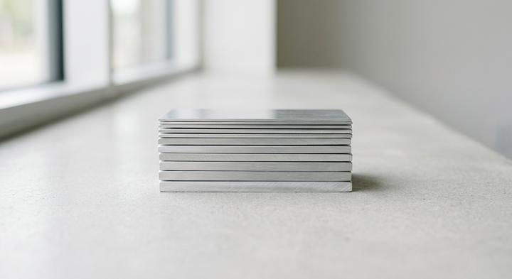
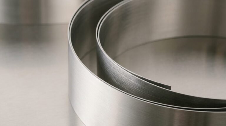
Different metal stamping applications require distinct tolerance strategies based on material gauge.
A QC lead staring at a 6:00 AM dimensional report can usually tell which designer pasted a standard tolerance block onto a print without checking the material gauge. Slapping the same blanket ±0.1 mm tolerance on a 4.0 mm structural bracket and a 0.15 mm shielding can is an easy way to inflate tooling costs or buy parts that do not fit. Heavy-gauge steels and ultra-thin foils behave differently under a press punch. If you do not adjust your inspection methods and tooling strategies to match the physics of each gauge, your assembly line will pay for it downstream during robotic welding or automated board placement.
Scenario A: Heavy Structural Brackets (Automotive & Industrial)
When you are running Heavy Structural Brackets through a high-speed progressive die, the immediate enemy is not tool wear—it is material springback. High-strength low-alloy (HSLA) steels have a habit of snapping back several degrees after ejection, meaning a flange that left the die at a perfect 90 degrees can settle at 87 degrees by the time it hits the container. If you are feeding these into a robotic welding cell, that three-degree deflection causes the arm to fault and lock up. We combat this at WenXinDa by engineering the progressive tooling with built-in overbend compensation, but you also need custom checking fixtures on the floor alongside the CMM to track how raw coil hardness variations shift that springback profile throughout a 50,000-unit run.
Scenario B: Thin Shielding Cans (Consumer Electronics)
For Thin Shielding Cans used in Consumer Electronics, the challenge shifts from structural strength to extreme coplanarity. These parts, often stamped from thin-gauge sheet metals under 0.2 mm, are so delicate that a traditional touch-probe CMM will physically bend the metal during the measurement cycle, giving you a false pass on a warped part. If a shield has even a 0.08 mm twist across its surface, it will sit unevenly on the PCB, causing open solder joints in the reflow oven. The fix is to bypass physical contact entirely; we utilize high-resolution laser scanning CMMs to map the entire flatness profile of these thin-gauge parts, protecting your surface-mount soldering lines from expensive post-assembly rework.
Scenario C: Medical Device Component Housings
Sourcing titanium or stainless Medical Device Component Housings adds cosmetic perfection and cleanroom sealing requirements to the metrology mix. Because these housings must meet hermetic seal standards while maintaining an unblemished aesthetic, any residual internal stress from the stamping process can cause delayed part warping during downstream passivation or sterilization. This means your inspection strategy has to track coordinate dimensions across the entire profile without touching—or scratching—the finished faces. The most reliable approach integrates high-speed automated optical inspection (AOI) directly into the packaging line, giving you 100% dimensional verification without human hands ever touching the sterile part.
Three Costly Misinterpretations of CMM Data in High-Volume Sourcing
The most expensive quality failures in high-volume stamping happen when procurement teams rely on static, cold-state measurements to predict dynamic, high-speed production behavior. In Volume Sourcing Misreading Coordinate data from a Coordinate Measuring Machine (CMM) is incredibly easy if your team treats a first-article inspection sheet as a static certificate instead of a single data point on a moving scale. Tooling heat, coil hardness variance, and progressive die wear shift dimensions over a run, meaning a part that measures perfectly on Monday can cause a critical line stoppage by Wednesday.
Assuming that a passing first-article layout of five samples guarantees the stamping tool will run 100,000 parts without thermal expansion issues.
A pristine five-part sample layout only proves the tooling works under slow-motion, static conditions. During continuous stamping at high speeds, friction generates significant heat within the die, causing punch clearances to drift and critical alignments to shift. If your progressive tool runs at high speed, thermal expansion will alter part geometry long before you reach the 100,000-part mark. Demand your supplier run a continuous pilot trial under real operating temperatures and track dimensional drift from the first stroke to the last.
Relying strictly on the CMM sheet’s pass/fail summary column while overlooking critical point-cloud trends that show localized material thinning.
A part can technically pass its dimensional limits while being on the verge of failure. If your team only scans the binary “Pass” column on a Coordinate Measuring Machine summary report, they will miss localized material thinning at the draw radius. When tooling wears, the metal thins dynamically, leaving you with parts that barely meet nominal thickness but are highly prone to fracturing during downstream welding. Insist on reviewing raw point-cloud trend lines because a dimension steadily creeping toward its lower tolerance limit is a clear warning that the die requires immediate maintenance.
Demanding tighter-than-necessary tolerances on non-functional dimensions, which inflates tooling wear and raises scrap costs without improving assembly fit.
Over-specifying tolerances on non-mating features or cosmetic surfaces does not improve part performance—it simply drains your manufacturing budget. Forcing a ±0.05 mm limit on a clearance pocket that could easily function with ±0.2 mm obliges the stamping plant to stop the press for tool sharpening three times as often. At WenXinDa, we guide OEM buyers to relax non-functional tolerances so they can concentrate their quality control budget on the key datums that actually control final assembly fit.
Vetting the Metrology Lab: What to Look for During a Factory Tour
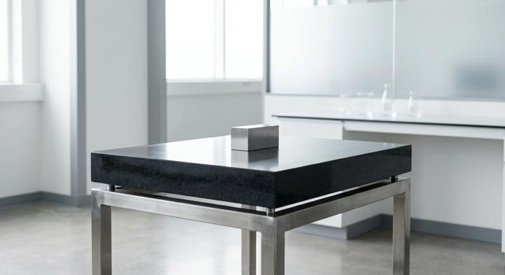
A properly controlled quality lab environment is crucial for reliable, repeatable dimensional measurements.
Designing a tight tolerance for an electronics enclosure or structural bracket is one thing; measuring it on a loud, vibrating factory floor is another. If a supplier’s quality room isn’t locked down, those tight limits on your print are nothing but wishful thinking. When auditing a stamping partner, do not let them wave you past the Metrology Lab with a nod toward a shiny machine. Look at the environment, the clamping, and how raw data flows to the final inspection sheet.
Metrology Lab Audit Checklist
| Ask | Expected Evidence | Red Flag | Responsible Party | Batch Variation Impact |
|---|---|---|---|---|
| How is thermal expansion controlled in the CMM room? | Dedicated room with automated HVAC keeping 20°C ±1°C and under 55% RH. Parts must soak for 24 hours before measurement. | Lab doors open to the stamping shop; parts brought straight from a hot die onto the CMM granite plate. | Lab Manager | Steel and aluminum expand with heat. Warm parts yield false dimensions, hiding stamping drift that jams assembly jigs downstream. |
| How are checking fixtures aligned to part datums? | Custom fixtures that clamp parts only on the functional assembly datums defined in your CAD drawing, certified to ISO standards. | Clamping parts on high-variability sheared edges or non-functional surfaces because the fixture was cheaper to build. | Tooling Engineer | Bad clamping masks physical part distortion. The fixture forces a bad part to look straight, but it springs back when released. |
| How does the operator handle raw inspection data? | Direct CAD-to-part point cloud comparison (.iges or .step) where software automatically generates deviation reports. | An operator manually typing coordinate readouts into an Excel sheet with a pen and notepad. | Metrology Operator | Manual data entry invites transcription errors, hides spikes, and makes real-time statistical process control impossible. |
| What is the Gage R&R standard for tolerances? | GR&R reports showing under 10% measurement variation across operators. | No formal GR&R data, or testing done with only one operator who “wiggles the part” to pass. | Lab Manager | High gauge variation means the supplier cannot distinguish actual tool wear from operator measurement style. |
| How often are CMMs calibrated? | Valid ISO/IEC 17025 accredited calibration certificate within 12 months, plus daily master ball verification logs. | Missing calibration stickers, expired certifications, or no daily check logs using a calibrated sphere. | Lab Manager | A drifting CMM yields systematically biased measurements, which invalidates your entire long-term process capability data. |
Aligning Datums Early: How to Protect Your Tooling Timeline with WenXinDa
While separating the tolerance rules for structural brackets and electronics enclosures keeps designs realistic, those boundaries only hold if your physical inspection fixture matches the assembly line from day one. Reaching a technical consensus on physical datums and CMM setup protocols before manufacturing starts is what prevents the costly, high-risk post-hardening tooling modifications that can easily push back a product launch by four to six weeks. In high-volume metal stamping, a minor mismatch between how a press operator nests a blank during production and how a metrology technician fixtures it on the CMM table yields false rejects and assembly-line failures. We eliminate this friction by integrating your GD&T parameters directly into the early tooling layout. By Aligning Datums Early—matching our temperature-controlled verification setups and physical inspection nests directly with your downstream robotic assembly line’s locating pins—we ensure that our measurements reflect your actual assembly environment.
This upfront coordination is how we Protect Your Tooling Timeline from the invisible tolerance stack-ups that stall automated lines. Rather than waiting for the first trial run to find out that the datum targets do not align, we run a complete manufacturability and alignment audit before cutting any tool steel. Share your 3D CAD files and target tolerance schemes with our engineering team; we will run a full technical review, evaluate metal stamping springback or thin-out risks, and design a custom sample checking plan to ensure your parts run predictably on your lines.