Custom Metal Stamping Specs: Optimizing Medical and Automotive Tooling for Tight Tolerances
Why Stamping Tolerances Define the Line Between High-Yield Runs and Costly Scrap
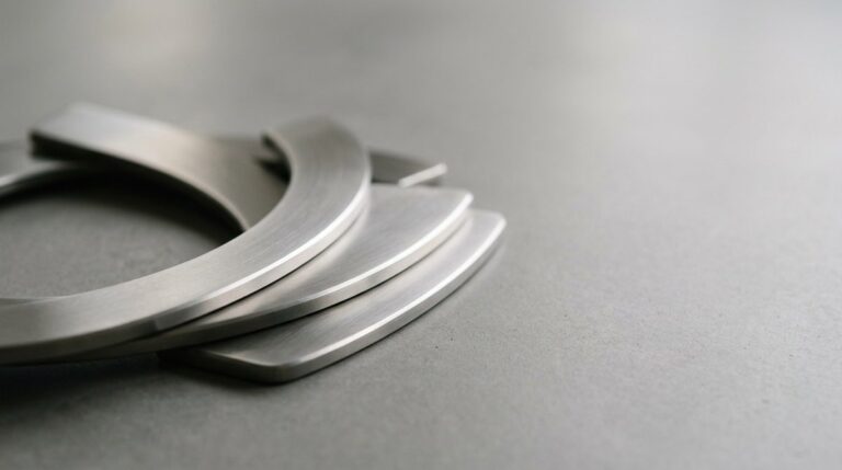
Achieving tight tolerances requires perfect alignment of material physics and tool design.
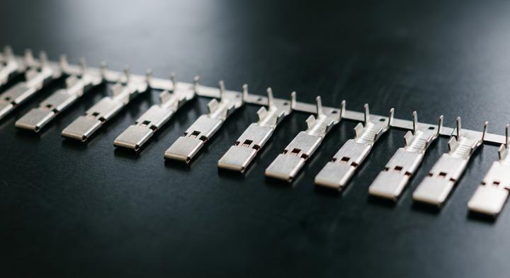
When a quality assurance manager rejects a batch of fifty thousand stamped contact pins, the root cause is rarely a press failure; it is almost always a mismatch between metal physics and progressive die design. In multi-stage configurations, tooling layout must calculate exactly how material shear strength and springback behave at every station. If the die design fails to compensate for how the metal behaves after the punch, a strip aligned perfectly at station one will drift by hundredths of a millimeter by station six. This progressive error causes misfeeds, accelerated tool wear, and costly downtime. As an experienced OEM and ODM partner, WenXinDa works with these mechanical realities daily: metal under tension does not read CAD drawings; it follows the physical limits of the coil.
This tension shapes different industry stress profiles. Medical stamping demands micro-scale precision where a micron’s deviation can compromise a critical drug delivery device. Conversely, automotive stamping focuses on structural durability under extreme heat and vibration, requiring repeatability across millions of cycles. In both fields, the largest procurement mistake is over-specifying. Requesting ±0.005 mm when ±0.02 mm is functionally sufficient can easily triple initial tooling costs. This tight spec forces the manufacturer to use slower wire-EDM processes, premium carbide inserts, and continuous manual adjustments, inflating your per-part budget without adding any real-world utility.
Balancing high-volume consistency with practical tolerances requires a partner who analyzes geometry before cutting steel. A seasoned manufacturer will identify where relaxing a non-critical dimension can salvage your yield rates and extend tool life. That is what separates constant troubleshooting from a predictable run. Before signing off on your next RFQ, remember this rule of thumb: specify tolerances to match the physical mating limits of your assembly, not the default settings of your CAD package.
Material Selection and Geometric Tolerances: The Designer’s Playbook

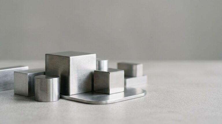
Quality inspection and material testing guarantee repeatability in high-volume production runs.
Which alloy should you specify for custom progressive die stamping when high electrical conductivity must coexist with razor-thin bend tolerances without micro-cracking?
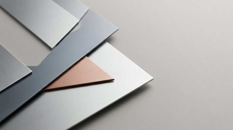
Selecting the right material grade is more than balancing yield strength and price; it dictates tool wear and geometric tolerance consistency. For high-volume runs, miscalculating the thickness-to-bend-radius ratio or ignoring grain direction when laying out parts in the strip guarantees micro-cracking along critical bend lines. At WenXinDa, we guide OEM procurement teams through this intersection of metallurgy and tooling feasibility to ensure predictable production yields and avoid field failures.
| Material Grade | Tensile Strength (MPa) | Minimum Bend Radius | Standard Tolerance Limit (mm) | Critical Application Detail |
|---|---|---|---|---|
| SUS 316L (Stainless Steel) | 485–580 | 1.0 to 1.5 × Thickness | ±0.05 | High corrosion resistance; ideal for sterile medical device assemblies under continuous chemical sanitization. |
| Beryllium Copper (C17200) | 680–1000 | 1.5 to 2.0 × Thickness | ±0.03 | Superior conductivity and spring force; ideal for automotive terminals and reliable battery contacts. |
| Aluminum 5052-H32 | 190–260 | 1.0 × Thickness | ±0.08 | Excellent strength-to-weight ratio; preferred for lightweight automotive brackets and electronic enclosures. |
| Brass (C26000 Cartridge) | 300–450 | 0.5 to 1.0 × Thickness | ±0.05 | Outstanding cold-working capacity; specified for non-sparking electrical pins and consumer hardware. |
Balancing Mechanical Limits and Production Yields
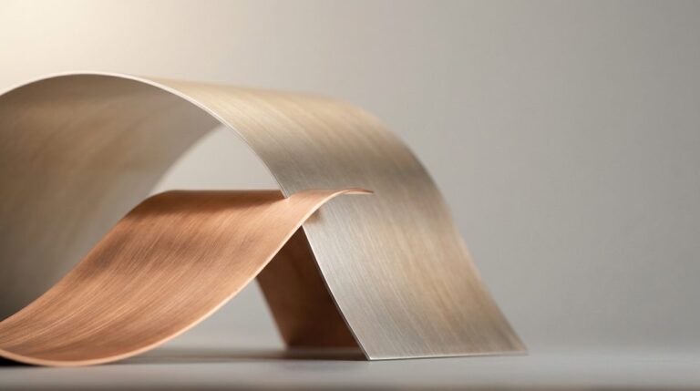
Evaluating formability is a balancing act between tensile strength and ductility. High-strength alloys resist deformation but are highly prone to springback and stress fractures during metal stamping. Softer options like aluminum 5052-H32 flow smoothly under the die but may fail under cyclic loading. For automotive electrical terminals, copper alloys dominate because they deliver the conductivity and elastic recovery needed to maintain tight pin retention over thousands of cycles. For medical hardware, the priority shifts: SUS 316L owns medical assemblies because its passive oxide layer survives autoclaving and maintains mechanical integrity when stamped into complex, ultra-thin surgical components. To prevent tearing, engineers must maintain a strict thickness-to-bend-radius ratio; dropping below the material’s threshold forces outer fibers beyond their tensile limit, creating micro-cracks that expand during heat treatment. To keep your progressive tooling running without unplanned downtime, always design your bend lines perpendicular to the rolling grain of the coil stock.
From Micro-Needles to Structural Brackets: Solving Specific Geometric Challenges
A quality control manager staring at a split titanium cannula under a 50x microscope at 6:00 AM knows exactly when the transfer press lubricant began to degrade. While aligning grain direction solves standard bending issues, scaling down to surgical micro-components or up to heavy-gauge automotive parts introduces entirely different physical limits.
Drawn Medical Shells
The medical device buyer faces a high-stakes bottleneck when trying to scale prototype stampings into clinical trial volumes without splitting the metal. For a startup trying to protect their FDA clearance timeline, choosing a single-action tool to save on upfront costs is a common trap; the raw material simply cannot stretch that fast without failing. At WenXinDa, we guide clients away from this risk by designing progressive transfer tooling that carefully controls material flow over multiple gradual stages. This slower, multi-die elongation keeps the walls uniform and maintains the critical ±0.01 mm dimensional tolerances without tearing the delicate titanium or stainless steel stock.
Stage Automotive Busbars Heavy Runs
A Tier-1 automotive procurement manager auditing an EV busbar line on a Tuesday afternoon is usually looking for one thing: how the supplier controls massive springback across 90-degree bends in heavy-gauge copper. High-conductivity copper resists clean deformation, meaning standard tooling steels will warp or chip long before the campaign hits a million strokes. To combat this, the progressive die must integrate precision coining at the bend radii to freeze the copper’s grain structure under immense tonnage, preventing the parts from twisting out of shape under continuous road vibration. The best defense against dimension drift here is requiring D2 or premium Vanadis tool steel inserts coupled with real-time, in-die tonnage sensors that halt the press before a bad part leaves the line.
Precision Coining and Embossing
When stamping Structural Brackets, adding localized stiffness through coining often creates a secondary headache—warping the entire flat plane of the bracket. A 400-ton mechanical press exerts so much localized pressure during coining that the displaced metal forces the surrounding flanges to bow, which subsequently derails the downstream robotic assembly line. To avoid this, tool designers rely on dual-action counter-embossing. Embossing When running heavy carbon steels acts as a tension release, flattening the part by pushing metal back in the opposite direction. To keep your line running smoothly, check whether your stamping supplier integrates physical limiters within the die shoe to control these coining depths precisely without over-stressing the press frame. The rule of thumb for flat brackets with heavy coining: if your coining depth exceeds 30% of the material thickness, demand counter-embossing features in the tool design to balance the internal stress before the metal ever exits the press.
DFM Failure Modes: Design Pitfalls That Destabilize Tooling Life
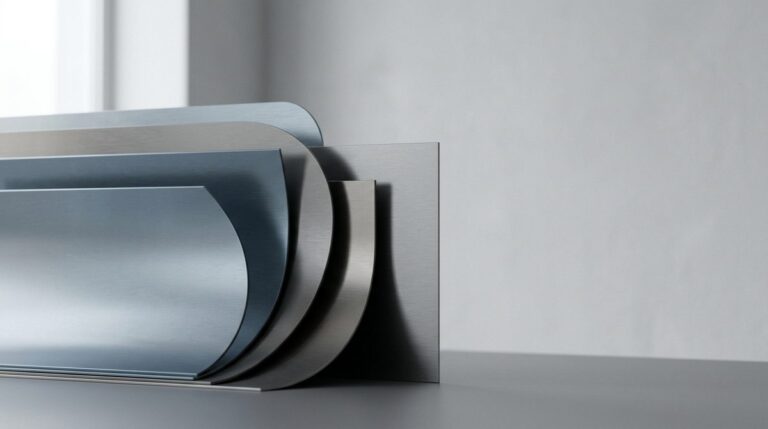
Optimizing geometric features like hole placement and bend radii prevents tool wear.
To avoid catastrophic tool wear, component geometries must respect the physical shear and flow limits of raw sheet metal before a progressive die is built. Many stamping issues blamed on material variation are actually DFM Failure Modes, caused by minor Design Pitfalls That Destabilize the stamping process and rapidly degrade tooling. To protect your long-term Tooling Life Tooling designers must evaluate how sheet metal flows, rather than treating the die as a brute-force cutter. By correcting these structural weak points during the initial CAD review, we keep production runs stable from the very first stroke.
A hole can be placed as close to a bend line as the flat blank layout allows.
Placing a round hole directly inside the material’s deformation zone turns it into an oval. During bending, the outer metal fibers stretch under tension, dragging the hole’s edge along. To keep holes round without extra sizing steps, the edge of the feature must sit at least twice the material thickness (2t) plus the bend radius away from the bend tangent. WenXinDa runs these clearances through simulated forming stages before cutting steel, catching interference long before a punch ever hits metal.
Sharp 90-degree internal corner angles yield a cleaner, tighter fit for mating parts.
Sharp internal corners act as high-stress concentration points that wear down punch tips and cause microscopic cracking along the part’s sheared edge. High-tonnage impact concentrated on a sharp corner accelerates micro-chipping, ruining both the component profile and the die surface. Swapping that zero-radius corner for a radius of at least 1.5 times the material thickness distributes stamping pressure across a broader area. If your assembly absolutely requires a dead-square fit, use a relief cut to clear the mating part’s corner without stressing the tooling.
Burr direction is a secondary cosmetic detail that can always be cleaned up in post-processing.
Treating burrs as a post-press cleanup problem ignores the reality of assembly tolerances and extra processing costs. Every blanking or piercing punch produces a burr on the exit side; if that burr faces an assembly mating surface, it prevents flush contact and acts as a point of wear or electrical shorting. Designing the tool layout so the burr naturally points away from critical contact surfaces removes the need for secondary deburring lines. It is far cheaper to orient the part correctly in the strip layout than to pay operators to manually deburr fifty thousand brackets on a Friday afternoon.
A single geometry check before tool design saves weeks of die tuning and costly trial-and-error loops.
Evaluating Precision Stamping Factories: Capabilities, Certifications, and Tooling Ownership
Now that the geometric and material challenges of forming micro-needles and structural brackets are resolved on paper, the commercial challenge is finding a precision stamping factory capable of executing those tolerances reliably over millions of cycles. For critical automotive and medical programs, a generic ISO stamp is no longer a sufficient gatekeeper to ensure part reliability.
| Certification or Capability | Automotive Mandate | Medical Mandate | Vetting Checklist for Buyers |
|---|---|---|---|
| In-House Tooling & Wire EDM | CPK studies > 1.67 for critical mating surfaces; progressive dies must survive millions of high-frequency strokes. | Ultra-precise micro-feature generation with zero burr allowance; specialized die surface coatings to prevent raw material galling. | Check if wire EDM achieves ±0.002 mm in-house. Red Flag: Outsourced primary toolmaking leading to 3-week engineering change order (ECO) delays. Responsible: Tooling Engineer. |
| Quality Management Systems (QMS) | IATF 16949 certification with full APQP, FMEA, and PPAP Level 3 document submissions. | ISO 13485 compliance, bio-burden monitoring, and rigorous lot control for Class II/III medical devices. | Request the latest third-party audits (SGS or TUV). Red Flag: Active certificates lacking verified registrar registration numbers. Responsible: QA Director. |
| High-Speed Inline Inspection | 100% automated optical sorting for safety-critical fasteners operating on active press lines. | Continuous inline laser micrometer measurement combined with automated vision validation. | Demand live demonstrations of automated CMM routines and active press sensors. Red Flag: Manual caliper spot-checks on runs above 100k units. Responsible: Lead Quality Inspector. |
| Tooling Ownership & Maintenance | Guaranteed lifetime cycle warranties with preventive maintenance logs integrated into the supplier’s ERP system. | IQ/OQ/PQ validation compliance and dedicated storage protocols to prevent environmental contamination. | Secure written agreements detailing die transfer rights and wear replacement terms. Red Flag: Hidden tooling storage fees or refusal to release dies. Responsible: Procurement & Legal. |
Streamlining the RFQ: What Engineers Need to Provide for Accurate Tooling Quotes
Resolving complex geometric challenges—whether maintaining micro-needle flatness or preventing springback on structural brackets—only matters if those engineering assumptions survive the transition into a commercial tooling estimate. In reality, most stamping quotes are delayed because the RFQ package treats the tooling shop as a psychic printing press. For toolmakers to calculate stable, low-maintenance progressive runs, they need a complete technical narrative. This is the core of What Engineers Need to put on paper before expecting Accurate Tooling Quotes. The foundational package starts with a clean 3D STEP file to verify mass and basic volume. However, the 3D model is only half the story. You must pair it with a fully detailed 2D drawing that specifies geometric dimensioning and tolerancing (GD&T) for critical datums, assembly mating faces, and any features that cannot be held to standard block tolerances. Without explicit GD&T, a toolmaker is left to guess which features require expensive, high-precision slide mechanisms in the die, leading to inflated contingency pricing.