Co-Designing Custom Hardware: How ODM Metal Stamping Accelerates Time-to-Market
Why Early Tooling Collaboration is the Only Real Shortcut to Scalable Metal Stamping
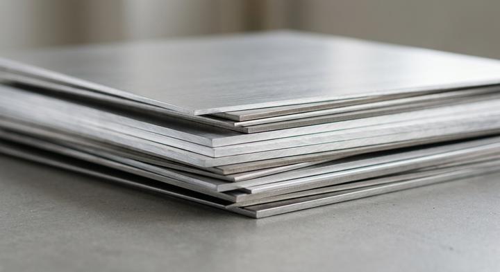
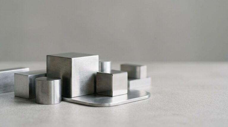
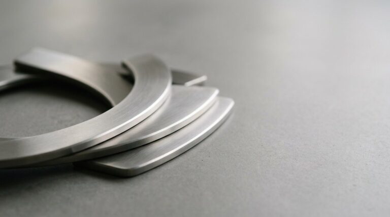
Selecting the right material grade and thickness is the foundational step of ODM metal stamping.
The friction in custom metal fabrication rarely comes from the raw tonnage of the press; it comes from the handoff between the CAD file and the tool shop. When a design team spends weeks tweaking a bracket or structural enclosure on screen, they work in an idealized, zero-tolerance vacuum. But metal is dynamic. When you force cold-rolled steel or aluminum into a 100-ton to 300-ton mechanical press, the material behaves like a plastic fluid. It stretches, thins, and springs back in ways that standard CAD packages simply cannot predict. When the first off-tool samples show up with a 0.08 mm variance, the stamping vendor blame-shifts to the secondary machining shop, leaving the buyer holding an expensive, out-of-spec pile of parts.
This mismatch is why early tooling collaboration isn’t a luxury—it is the only way to avoid rebuilding dies after they have already been cut. If progressive die layout, laser blanking, and secondary CNC machining are split across three different subcontractors, tolerance stack-up is guaranteed. One shop optimizes for their laser tolerances, the next for their press feed, and the third for their fixture alignment. At WenXinDa, founded in 2010 in Dongguan, we run all three processes under one roof specifically to stop this finger-pointing. When our tooling R&D engineers sit down with your design team before a single block of tool steel is cut, we look for the practical realities that software misses: thin-wall weaknesses, un-stampable radiuses, and progressive layouts that do not leave enough material ribbon for stable feeding.
Catching these issues early alters the entire economics of the project. Modifying a 3D model takes ten minutes; modifying D2 or SKD11 tool steel after hardening requires wire EDM, welding, or starting over completely. Our engineer-to-engineer reviews verify that the progressive die stations can actually form the required geometry across a 50,000-part run without premature tool wear. A practitioner’s rule of thumb: if your stamping supplier accepts your CAD file without questioning a single bend radius or material specification, they aren’t saving you time—they are just deferring the redesign costs to your first production run.
Tooling Metrics and Material Physics: Defining the Stamping Strategy Before RFQ
How do you calculate the exact point where temporary stage tooling becomes more expensive than a progressive die?
While volume is the default baseline for amortization, the transition from manual Stage Tooling and Modular Dies to high-volume progressive dies is actually governed by a mix of material behavior, lead times, and post-stamping finishing tolerances. Choosing the wrong tooling class based purely on part count ignores how metal behaves under tonnage, especially when post-plate thickness changes the final dimensions. The matrix below shows how these variables interact across different production scales before you lock in an RFQ.
| Production Phase | Tooling Class | Typical Tooling Lead Time | Practical Dimensional Tolerances | Recommended Finishing Sequence |
|---|---|---|---|---|
| Low-Volume (100 to 2,500 pcs) | Stage Tooling / Modular Dies | 15 Days | ±0.20 mm | Post-stamping plating or powder coating (bare edges are sealed, but manual handling increases labor) |
| Bridge Run (2,500 to 10,000 pcs) | Compound Dies / Semi-Auto | 25 Days | ±0.15 mm | Inline deburring followed by post-plating (balances tooling costs & manual handling) |
| High-Volume Scaling (10,000+ pcs) | Progressive Dies | 45 Days | ±0.10 mm | Pre-plated raw coil stock or post-forming plating (tooling geometry compensates for coating buildup) |
Balancing Material Physics with Post-Plate Realities
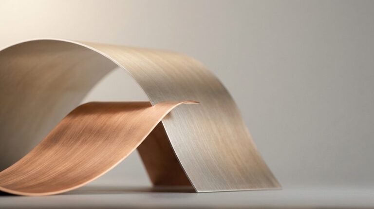
If you are stamping 5052 aluminum, its low yield strength means high springback—often requiring the die designer to over-bend features by 5 to 7 degrees just to hit a clean 90-degree angle. Compare that with SPCC cold-rolled steel; it holds its shape better but tears through standard D2 die steels much faster, driving up your maintenance costs if the tool isn’t coated or hardened.
Then there is the plating trap. If your drawing calls out a tight tolerance of ±0.05 mm on a critical bracket but your finishing spec requires a 5-micron zinc plating or a 50-micron powder coating, you cannot hand your raw CAD file to a toolmaker and expect it to fit. At WenXinDa, our tooling design team works backward from the finished, plated state, modifying the die dimensions so the stamped metal accounts for finish buildup. For instance, a drawing that ignores a 50-micron powder coat will result in a part that is 0.10 mm out of spec once it leaves the curing oven.
Always force the toolmaker to state on the print whether their tolerances apply to the raw metal blank or the final, plated part.
Operational Fit: Matching Production Volume to Stamping Machinery
Progressive die stages require precise physical alignment to ensure repeatable geometric tolerances.
A stamping press operator halts a 200-ton line at 6:00 AM because a carrier strip of 0.8 mm cold-rolled steel buckled inside the progressive die. This shutdown wasn’t a press failure; it was a design team assuming a carrier web built for low-stress laser cutting could survive mechanical feeding. Moving from prototype to production changes how metal behaves under stress. Aligning your volume to the correct tooling and stamping machinery keeps the program on budget. At WenXinDa’s Dongguan facility, we look past the idealized CAD model to see how the strip behaves when gripped, pulled, and struck hundreds of times a minute.
Scenario A: Low-Volume Production Runs (1,000 to 5,000 units with modular stage tooling)
For Volume Production Runs of 1,000 to 5,000 units, paying progressive die premiums is a commercial mistake. Instead, low-volume brackets or enclosures rely on modular stage tooling, where an operator manually transfers the blank across independent presses. Because these dies are simple, modifying them for design revisions is fast and cheap. The trade-off is higher labor cost and slower cycle times, but this beats a massive tooling expense that never amortizes. Here, the focus is strictly on minimizing manual stroke cycles.
Scenario B: High-Volume Industrial Scaling (50,000+ units on fully automated progressive lines)
Once a program transitions to Volume Industrial Scaling of 50,000 units or more, manual handling compromises dimensional repeatability. High-volume runs demand automated progressive dies, where a continuous metal coil feeds through synchronized stations in a single press. Every stroke performs multiple cutting, piercing, and forming operations, ejecting a finished part. The heavy upfront die cost is rapidly amortized by negligible per-unit labor. This setup leaves no room for feed slip, requiring straighteners on the decoiler to prevent misfeeds that could smash high-precision carbide tooling.
Scenario C: Adjusting the Flat Pattern (adapting laser-cut prototypes for progressive press feeding)
Transitioning from a laser-cut prototype to a high-volume stamped part is never a 1:1 conversion. Laser cutting nests parts tightly on a sheet with almost zero waste, but progressive stamping requires a continuous carrier strip to pull the material. Adjusting the Flat Pattern means redesigning scrap strip layouts and micro-joint placements to transition smoothly from laser prototyping to progressive press feeding. Without these adjustments, the thin metal holding the part to the strip twists, leading to feeding jams. It is far cheaper to design these carrier webs early than to recut hardened tool steel after the die is built.
When planning your tooling strategy, remember that your initial prototype flat layout exists to prove out the geometry, while your production flat layout exists to survive the physical force of the press.
Three Drawing Errors That Crack Dies and Stall Stamping Runs
A beautifully rendered STEP file will still split a progressive die if the drawing ignores the physical grain of the raw coil or the elasticity of the alloy. These mechanical oversights can Stall Stamping Runs. Three specific drafting errors consistently destroy progressive tooling on the shop floor.
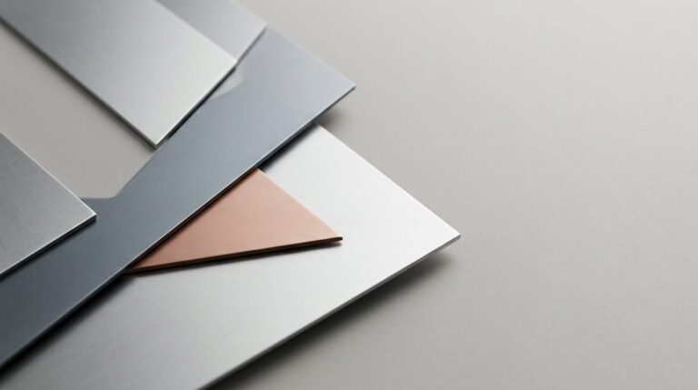
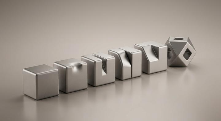
Bends can run in any direction as long as the blank nest maximizes material yield on the strip.
Bending sheet metal parallel to the rolling grain concentrates tensile stress along a single crystalline boundary, propagating deep micro-cracks along the outer radius of temper-rolled alloys like SUS301-CSP or 5052-H32 aluminum. If your flat-pattern nested layout isn’t explicitly oriented perpendicular or at least 45 degrees to the coil’s rolling direction, the metal will split during high-speed runs. Tooling designers must overlay the grain direction directly onto the progressive strip layout before EDM wire-cutting the die blocks, even if it drops material yield by a few percentage points.
Modern CAD software automatically resolves corner geometries without requiring manual bend reliefs.
Relying on default CAD sheet metal features often creates zero-clearance transitions where a flange bend meets an unbent face. Under the press, this oversight tears the metal web, throwing severe lateral thrust loads back into the punch edges and prematurely wearing the die. A real bend relief—ideally a circular or rectangular cutout with a width of 1.5 times the sheet thickness and a depth exceeding the bend radius—allows the material to deform cleanly. Do not assume your software modeled this; verify that these reliefs are actual cutouts in the STEP file, not just virtual lines.
Modeling a part to the exact target 90-degree angle ensures the stamped part will hold that shape.
Every alloy has an elastic limit that forces the metal to spring back once the punch retracts. Mild SPCC steel might only bounce 1 to 2 degrees, but high-strength low-alloy (HSLA) steels or hard-temper brass will spring back up to 10 degrees depending on the bend radius-to-thickness ratio. The designer should not attempt to pre-compensate this on the part drawing; instead, the toolmaker must design overbend stations or bottoming steps directly into the progressive tool. When we run these parts at WenXinDa, our tooling engineers calculate springback based on actual coil batch tensile tests to avoid iterative, expensive die recutting.
The physical grain and elasticity of the metal always win against an unverified CAD model.
Vetting the Factory Floor: How to Audit a Stamping Supplier’s Assets
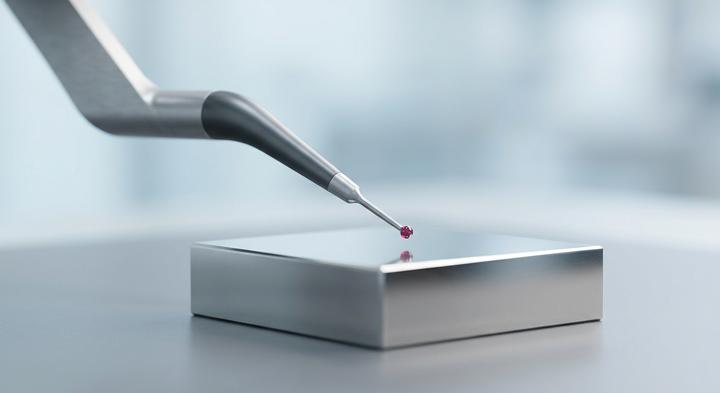
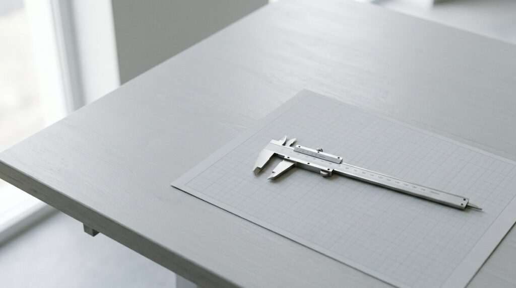
Verifying dimensions against defined drawing datums ensures consistent production quality.
Even the most mathematically perfect drawing will fail on the shop floor if the metal stamping supplier lacks the physical assets and quality control infrastructure to execute it. While any broker can present a glossy ISO 9001 certificate, a true manufacturing partner must back up their capabilities with real-time tooling logs, material trace records, and verifiable calibration data.
| Audit Focus Area | Required Proof Document | Middleman Red Flag | Procurement Verification Steps |
|---|---|---|---|
| Tooling & Die Maintenance | Maintenance logs tracking die hits, regrinding cycles, and active spare component inventories. | Missing logs; “on-demand” tool maintenance with no system for tracking progressive tool wear. | Ask the supplier to show the live maintenance schedule and hit counts for an active production job. |
| Material Traceability | Raw material heat numbers, mill certificates, and third-party chemical spectrum analyses for each batch. | Generic material sheets lacking mill stamps, heat numbers, or traceable batch codes. | Request the specific mill certificate for the raw coil currently loaded onto the press feeding line. |
| Metrology & Inspection | Dimensional measurement reports tied directly to Coordinate Measuring Machine (CMM) data and drawing datums. | Manual hand-caliper sheets containing generic pass/fail stamps instead of raw digital coordinate data. | Verify that the inspection reports map back to your defined critical-to-quality (CTQ) datums. |
A paper-only trading company cannot show a live calibration curve or pull up a progressive die’s maintenance history on a Tuesday afternoon. Direct manufacturers solve this by embedding metrology directly into the workflow. WenXinDa handles quality control by providing dimensional measurement reports tied directly to coordinate measuring machine (CMM) data and customer drawing datums. To bypass middlemen and verify physical asset capability firsthand, hardware procurement teams can submit their drawings to the WenXinDa engineering team for a transparent tooling review and factory-direct RFQ.
From CAD to First Off-Tool Samples: Locking Down Your Production Schedule
Press tonnage and raw mechanical capabilities are only half the battle. The true risk to an export delivery timeline is the fragmented handoff between separate tooling, stamping, and finishing vendors. When a custom stamped enclosure requires secondary CNC milling or specific surface treatments, split-vendor supply chains inevitably lead to finger-pointing. The plating house blames the stamping shop for out-of-tolerance parts, the stamper blames the toolmaker, and your assembly line sits idle. Consolidating these disciplines under one roof directly insulates your schedule. With a 15-year history of export manufacturing from our facility in Dongguan, China, WenXinDa integrates the entire production cycle to eliminate these administrative friction points.
Our facility coordinates stamping press lines up to 300 tons with a dedicated, in-house wire EDM tooling shop, secondary CNC machining center, and assembly bays. Keeping our toolmakers three doors down from the press operators means that when a progressive die requires micro-adjustments for material springback or plating preparation, the modification happens in hours rather than stalling production for weeks of multi-party email chains. This physical proximity secures your manufacturing Schedule While protecting the dimensional integrity of your components from the first stroke to final delivery.
We do not expect you to sign off on tooling costs based on generic estimates. Instead of an automated quote, we invite your engineering team to upload your 3D CAD files in STEP, IGS, or DXF formats for a thorough design for manufacturability (DFM) review. Our in-house engineers will review your part geometries, suggest material utilization improvements to reduce raw-material costs, and provide an upfront tooling quote. This upfront engineering assessment ensures we catch potential forming issues early, keeping the path clear to deliver accurate First Off Tool Samples without costly downstream modifications.