Industrial Equipment Components: Sourcing Corrosion-Resistant Metal Stamping and Secondary Platings
Why Drawing-Board Metal Stamping Designs Fail Under Harsh Industrial Stress
A heavy-duty mounting bracket can look flawless on a Monday morning receiving-dock inspection—perfect dimensions, clean plating, and a correct alloy certification sheet. Yet three weeks later, that same bracket splits clean down its bend line under high-amplitude motor vibration. This is the quiet breakdown in custom metal stamping procurement: parts that meet the print on paper often harbor microscopic material damage that standard QC sheets never catch. When punch-to-die clearance is slightly off for high-tensile alloys, the shear action leaves micro-fractures along the cut edges. Under continuous operational stress, these tiny, jagged tears act as stress concentration points, propagating rapidly into fatigue failures.
Failure risk climbs when components face aggressive environments like chemical processing plants, marine infrastructure, or heavy industrial machinery. Cold-working stress from tight bend radii creates concentrated, high-residual-stress zones. When these zones encounter halides, road salts, or chemical washdowns, stress corrosion cracking (SCC) causes the metal to split prematurely. Fixing these issues after the tool steel is cut is an expensive, project-stalling mess. Trying to weld, grind, or spark-erode a hardened D2 or DC53 tool steel die can easily run into thousands of dollars in tooling shop rework and weeks of line-down delays. Correcting a flat pattern or adjusting a bend radius on a CAD screen, by contrast, costs virtually nothing.
The supplier must act as an engineering gatekeeper before machining begins. At WenXinDa, we have built custom tooling in-house since 2010. We have learned that the most valuable part of a quote isn’t the unit price; it is the upfront design for manufacturability (DFM) review. Our engineering team flags metal flow restrictions, excessive springback, and high-draw thinning before we cut hard tool steel. For any high-stress industrial application, the most reliable risk-mitigation step a buyer can take is to demand a simulated thinning and springback analysis with the tooling quote, rather than waiting for physical samples to crack on a vibration table.
Alloys and Secondary Platings: Specifying Stamped Parts for Salt, Chemical, and Marine Environments
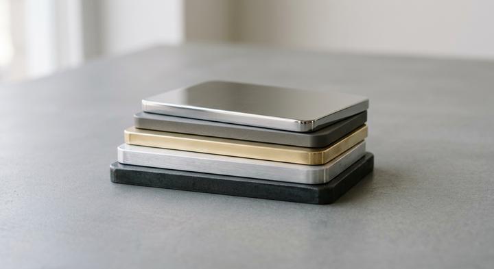
Selecting the right alloy and surface finish is critical to preventing industrial stress corrosion.
When engineering hardware for Marine Environments, how do you balance raw alloy costs against the micro-dimensional changes of protective coatings?
If you ignore the tool steel iron residue left on stamped 316L stainless steel, your premium parts will pit within weeks unless you run them through a nitric or citric acid passivation bath. For non-stainless metals, secondary platings like Zinc-Nickel provide exceptional protection but change your dimensions enough to seize up threads during final assembly. At WenXinDa, we run the numbers on plating buildup during the initial DFM review to ensure critical tolerances survive the coating bath.
| Industrial Application | Base Metal Grade | Recommended Plating | Corrosion Resistance (Salt Spray Hours) | Critical Tolerances | Verdict & Fit |
|---|---|---|---|---|---|
| Saltwater Enclosures (Sensors, Outdoor Junction Boxes) | 5052-H32 Aluminum | Type III Hardcoat Anodizing (MIL-A-8625) with a Teflon Seal | ASTM B117 compliance: 1,000 to 1,500 Hours | Thickness increases by 0.025 mm to 0.050 mm per side; high risk of thread galling and edge blowout on sharp corners. | Best for lightweight structural brackets where weight limits justify anodizing costs. Parts must feature minimum 0.8 mm radii to ensure uniform coating coverage. |
| Chemical Processing Equipment (Acidic/Halide Washdowns, Valves) | 316L Stainless Steel | Citric Acid Passivation (ASTM A967 / AMS 2700 Method 2) | ASTM A967 compliant: 1,500 Hours + | Zero dimensional change; must neutralize microscopic iron transferred from D2/DC53 stamping dies. | Mandatory for corrosive acid exposure. Passivation cleans tool steel residue off sheared profiles, preventing localized micro-pitting. |
| Outdoor Utility Hardware (Power Line Brackets, Heavy Mounts) | Cold-Rolled Carbon Steel (SPCC/1010) | Zinc-Nickel (Zn-Ni) Electroplating (12-16% Nickel Alloy) | ASTM B117 salt spray: 1,000+ Hours to red rust | Predictable 8 to 15 microns (±0.003 mm variance on 16% alloy); high risk of thread interference on M4-M8 internal threads. | Most cost-effective high-strength structural choice. Avoids the heavy, highly uneven buildup of hot-dip galvanizing on critical dimensions. |
Designing for Plating Tolerances
The biggest trap in high-volume metal stamping is forgetting that electroplating deposits are never perfectly uniform—zinc-nickel will build up twice as fast on sharp outer corners as it does deep inside a tapped thread. If your drawing specifies a standard M6 thread without a 4x plating thickness allowance, the mating fastener will seize halfway in during final assembly, forcing you to tap the parts again manually on the factory floor. When specifying close-tolerance parts for marine use, always oversize internal threads by four times the plating thickness to prevent assembly seizure and early corrosion failures.
Matching Stamping Methods to Volume: Progressive Dies vs. Stage Tooling
The stamping press operator at 7:00 AM stands over a stack of manual transfer brackets, counting the seconds spent loading each blank into a single-station press. When choosing how to manufacture your components, matching stamping methods to your real-world production volumes is what keeps your unit costs from spiraling. For short-run programs, a project can start and stay on Stage Tooling. The initial capital layout remains low, but the labor rate of manual hand-off will eventually cannibalize your margin as the order grows. Transitioning to Progressive Dies running at speeds up to 120 strokes per minute at WenXinDa removes the human variable, pulling coiled strip through several stations to stamp, bend, and blank a finished part with every cycle.
Volume Heavy Equipment Brackets
When a heavy-duty machinery project requires fewer than 5,000 thick-gauge mounting plates a year, paying forty thousand dollars for a complex progressive tool is hard to justify. For these lower volumes, running single-station gang dies or offline CNC punching keeps upfront tooling capital minimal while handling the heavy forming requirements on beefier, slow-speed presses. Although manual handling of each sheet increases the per-unit labor cost, the total cost of ownership stays lower because the tool path is inexpensive to build, easier to modify, and highly forgiving of mid-year engineering changes.
Volume Structural Brackets
The math shifts entirely when a contract jumps to 60,000 units, as a mid-tier HVAC manufacturer recently experienced when their Q3 demand spiked. They were caught running parts across three slow, manual press lines, watching their labor costs skyrocket and their lead times slide out by weeks. Moving that part to a progressive die consolidated three manual steps into a single continuous-strip operation, clearing their production backlog in four days. The massive upfront tooling investment pays for itself rapidly by driving the cycle time down to seconds and removing the manual transfer step entirely.
Complex Multi-Station Tooling: Bend Electronic Shields When Wear Strikes
For intricate parts requiring multiple tight radii and narrow web widths, running a Complex Multi-stage tool at high speed places extreme thermal stress on individual punches. With high-density Bend Electronic Shields when tool wear becomes a constant risk, a supplier without an on-site toolroom will keep your line down for days while shipping dies out for simple sharpening. Having built-in toolroom capability means our engineers handle rapid tool sharpening, punch replacements, and immediate die maintenance on the shop floor, keeping down-time under an hour.
If your annual projection crosses 15,000 units, the manual labor overhead will almost always eclipse the upfront die cost before you reach your first design revision.
Four Costly Sourcing Blindspots in Industrial Metal Stamping Specifications

Correcting design geometry in the early stages prevents high-cost failure during stamping.
A CAD drawing behaves perfectly. A coil of cold-rolled steel under a 200-ton press does not. When sourcing teams treat sheet metal as an idealized, uniform medium, they write high scrap rates and premature tool wear directly into their wholesale unit costs. Real-world metal stamping requires adjusting drawing-board specifications to account for the physical limits of raw alloys under heavy tooling.
-
Blindspot 1: Bends can run in any direction on the sheet layout to maximize nesting yield.
Cold-rolling mills stretch the metallurgical grain structure of sheet metal along a single axis. If you fold a bend parallel to this rolling direction, the outer radius is highly likely to split or develop micro-cracks under load. To prevent structural failures, engineering drawings must explicitly orient critical bends perpendicular, or at least 45 degrees, to the rolling grain. While nesting parts diagonally might lower your raw material yield by up to 8%, that minor material premium is a fraction of the cost of a full batch rejection or a product recall. -
Blindspot 2: Simply calling out “zinc plating” on the drawing is enough to prevent outdoor corrosion.
Writing “zinc plating” on a print without context is an invitation for the cheapest possible finish—often a thin 3-micrometer flash with no passivation that rusts after its first rain. To get what you actually need, specifications must cite a recognized standard such as ASTM B633, along with the correct service condition class and supplementary chromate treatments. For outdoor industrial hardware, you should explicitly call for a minimum thickness of 12 micrometers to ensure the zinc sacrificial barrier lasts under exposure. -
Blindspot 3: Holding tight tolerances across the entire part profile guarantees a higher-quality assembly.
Overspecifying non-functional features—such as demanding ±0.05 mm tolerances on standard clearance holes—drives tool maintenance costs through the roof without adding value. It forces the line to pull and service dies constantly to clean up normal edge burrs and punch wear. At WenXinDa, we guide clients to limit tight tolerances strictly to functional mating surfaces, letting standard clearance zones utilize wider commercial limits to keep the tooling running smoothly. -
Blindspot 4: Sheet metal stretches uniformly into deep cavities without changing the nominal wall thickness.
This assumption ignores physical material flow; deep-drawing thin sheets causes substantial thinning at key vertical transition radii, risking catastrophic tears under continuous field vibration unless wall reduction allowances are modeled from the start.
Auditing the Stamping Shop: How to Verify Metrology and Traceability Beyond the Certificate
Once you select progressive dies or stage tooling to balance your tooling amortization, physical consistency on the factory floor relies entirely on active quality control rather than passive approvals. An ISO registrar can stamp a paper Certificate Once, but preventing downstream assembly failures requires looking past PDF attachments to verify active metrology and raw heat logs.
| Audit Checkpoint | Verifiable Evidence | Common Red Flags | Mitigation Action |
|---|---|---|---|
| Heat Traceability | Original Mill Test Reports (MTRs) detailing exact chemical composition and mechanical yield/tensile strength, matched to coil heat numbers physically stamped on job travelers. | Generic, un-stamped material certs; heat numbers on the factory floor that do not match the incoming master coil log or the travelers at active press lines. | Mandate that operators stamp or write the master coil heat number directly onto the route traveler sheet at every shear, blanking, and press station before runs begin. |
| In-Process SPC Tracking | Hourly X-bar and R control charts showing dimensional drift for critical tolerances; live digital calibration logs and touch-trigger probe data from coordinate measuring machines (CMM). | Handwritten SPC charts with suspicious, perfect center-line stability and zero variance, or logs filled out in the exact same handwriting across three separate shifts. | Bypass paper logs and audit the raw, time-stamped digital database outputs directly from the CMM software to verify operator measurements match floor tracking. |
| Export Oxidation Prevention | In-house packaging specifications requiring heavy-duty 4-mil Vapor Corrosion Inhibitor (VCI) bags, custom corrugated dunnage, and calibrated industrial desiccant packs. | Oily parts packed loose in unlined wooden crates or standard cardboard boxes with cheap stretch wrap, offering zero moisture or salt-air barrier during ocean shipment. | Mandate vacuum-sealed VCI barrier wrapping for all ocean containers; specify exact desiccant pack weight requirements calculated per cubic meter of cargo volume. |
At WenXinDa, we build this floor-level transparency directly into our daily production. We pair every production run with its raw material heat records, maintain digital SPC records directly from our CMM database, and pack ocean-bound parts in heavy-duty VCI bags with calculated desiccant loads to prevent salt-air rust. Our engineers help you move beyond paper certificates to verify actual quality at the press.
Tooling Timelines and DFM Boundaries: Partnering with WenXinDa
Deciding between progressive dies and stage tooling is only half the battle; the real friction begins when transitioning those digital designs into physical tool steel. At WenXinDa, we skip the front-office sales brokers and hand your drawings directly to the tooling engineers on our shop floor. When you submit a 3D STEP file, our engineers do not just run an automated software sweep. We conduct a hands-on design for manufacturability (DFM) review to analyze material flow, map localized thinning under deep-draw geometries, and calculate real-world springback margins for high-strength alloys. Finding a plating clearance bottleneck or assembly interface on screen is the difference between a simple CAD modification and a scrapped die block. Catching these boundary issues early protects your tooling capital before our machining center cuts into expensive tool steel.
Once those part geometries are validated, we kick off our 20-to-30-day Tooling Timelines. This schedule spans CAD sign-off, CNC die block machining, wire EDM cutting, vacuum heat treatment, and the initial trial runs on our presses. We do not skip steps or rush the heat treatment to meet arbitrary deadlines; a rushed tool is simply one that deforms early on the production line. This workflow concludes with physical press trials and the delivery of a rigorous First Article Inspection (FAI) report, where we physically measure the stamped parts against your 2D specs to prove the tool behaves under actual production pressure. To see how your design translates to the press, upload your 3D CAD files in STEP format and your 2D engineering drawings. Our engineering team will run a complete DFM review and return a transparent tooling quote.