Automotive Metal Stamping Sourcing Guide: Auditing Supplier Process Stability and PPAP Readiness
Why Press Stability and Toolroom Discipline Matter More Than Unit Price
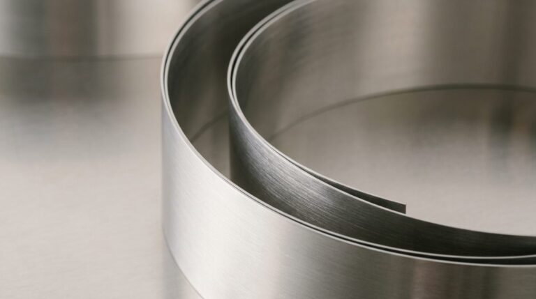
When a robotic welding cell on a Tier 2 automotive line jams, the clock starts eating ten thousand dollars of margin an hour. The root cause is rarely a sudden, catastrophic press failure. More often, it is a slow, invisible drift in part-to-part thickness that went unnoticed during a high-speed run. Sourcing teams frequently sign off on metal stamping contracts based on pristine, hand-polished prototype parts. These first-article “golden samples” are run slowly under perfect, artificial toolroom conditions. They mask the thermal expansion and cumulative punch wear that show up once a progressive die hits 80 strokes per minute on a continuous, multi-day run.
A progressive tool’s clearances only need to drift by a hundredth of a millimeter to trigger downstream chaos. When parts drift, automated assembly lines suffer from misaligned mating surfaces, erratic weld spatter, and feed-line jams. A cheap piece-price quote instantly evaporates when you factor in manual sorting, expedited freight, and emergency tool modifications. This is why looking at the bottom line requires assessing the total Cost of Poor Quality. In high-volume metal stamping, operational continuity and press reliability dictate your actual cost profile far more Than Unit Price At the sourcing stage.
To run high-volume jobs successfully, the toolroom must coordinate progressive tooling design directly with PPAP Level 3 requirements. At WenXinDa, we align initial dimensional capability data against the mating assembly’s actual tolerance stack-ups. This allows our toolroom to establish realistic, data-driven wear limits long before the first steel coil is loaded into the press. When auditing any stamping partner, skip the showroom display cases. Ask to see their tool-maintenance logs on a high-volume program that has already run past 300,000 cycles—that is where the real capability is documented.
Beyond the Brochure: Verifying Press Capacity, Tool Steel Grades, and Sensor Systems

Precision tool steel design demands modular stability to prevent dimensional drift over high-volume production cycles.
How do I verify a metal stamping supplier’s actual press capacity and tooling wear limits during a factory audit?
To protect high-precision progressive runs from costly downstream failures, sourcing teams must look past nominal machine lists and inspect the physical margins on the factory floor. Running a progressive die at or near 90% of a press’s rated tonnage causes structural frame deflection and severe vibration, which rapidly misaligns pilot pins and accelerates cutting-edge wear. A stable manufacturing process requires conservative load buffers, real-time in-die sensors, and high-performance tool steel selections that can handle hundreds of thousands of cycles without dimensional drift.
| Buyer Component Class | Key Decision Factor | Automotive Baseline Requirement | Primary Shop-Walk Risk | Supplier Process Standard |
|---|---|---|---|---|
| High-Volume Terminals & Connectors | Tool Steel Grade for Cutting Inserts | Powder metallurgy steels like ASP-23 or Vanadis 4 to resist chipping on high-speed runs | Standard D2 or SKD11 wearing down rapidly, causing heavy burrs after only 80,000 strokes | Premium PM-grade steel inserts used on all high-wear cutting stations; tool life guaranteed up to 1,000,000 cycles |
| Structural Automotive Brackets (Up to 6mm) | Press Load Margin & Frame Deflection | Rated press tonnage selected to ensure running loads do not exceed 70% capacity | Frame twisting and bolster bending when running heavy structural parts near machine limits | Press allocation restricted to a maximum of 65% of rated capacity on heavy-gauge progressive programs |
| Critical Safety Assemblies (Zero-Defect Goal) | In-Die Process Control & Metrology | Continuous Cpk ≥ 1.67 on critical-to-quality dimensions; automated part inspection | Bypassed or missing in-die sensor systems; process capability measured only on ideal first-article runs | Fully integrated electronic in-die tonnage monitors and optical misfeed sensors on every progressive die |
Securing the Production Run
Sourcing teams should audit how a factory manages in-die protection and tonnage monitoring before signing a purchase order. When an unmonitored die encounters a misfeed or a double-sheet condition, the resulting crash destroys weeks of progress and tens of thousands of dollars in tool steel. Evaluating these variables under running conditions ensures that a technical partnership with WenXinDa is built on stable mechanical realities rather than sales promises.
Always ask to see the active load-cell readouts on a running press to ensure the tooling is pulling no more than 70% of the machine’s rated tonnage.
Choosing the Right Tool: Progressive Dies vs. Transfer Tooling for Your Part Geometry
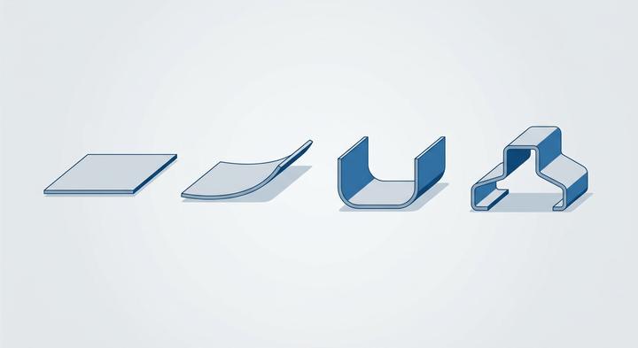
A stylized look at sequential forming layout, balancing structural material flow and tool capabilities.
The QC engineer at 6:00 AM on a Tuesday walks the press floor, measuring a micro-fracture along a deep-drawn collar that split because the line speed was pushed past forty strokes per minute. This split is the classic signature of a component forced into the wrong tooling family. While high-speed Progressive Dies excel at rapid throughput, certain profiles—especially those with tall vertical walls—will physically rip if you force them to remain attached to a carrier strip. When assessing Your Part Geometry The decision between progressive and Transfer Tooling comes down to how the metal must flow to prevent thinning. At WenXinDa, we run these geometric feasibility checks before cutting tool steel, ensuring the physical limits of the raw material dictate the stamping method rather than a default machine preference.
High-Speed Progressive Lines for Contacts and Terminals
For high-volume production of small, tight-pitch components like electrical Terminals When a buyer needs 500,000 units a week, we configure our high Speed Progressive Lines to maintain sub-millimeter pitch control. The parts remain attached to the continuous metal carrier strip as they fly through consecutive stations at up to 120 strokes per minute, meaning there is zero chance for misalignment. If you tried to handle these tiny parts with transfer arms, the physical grippers would simply drop them or distort the delicate brass or copper tabs.
Transfer Dies for Deep-Drawn Shells and Housings
When stamping deep-drawn cylinders, tall cans, or industrial Housings When a part requires vertical walls deeper than 50mm, a progressive carrier strip becomes a massive liability. The metal cannot stretch far enough without tearing, so we must cut the blank free at station one and use Transfer Dies to mechanically pass the loose cup from one draw stage to the next. This mechanical hand-off lets the material flow naturally into the die cavity from all sides, preventing the severe wall-thinning and splitting that occurs when you try to force deep Drawn Shells to stay anchored to a rigid carrier strip.
Progressive Heavy Bracket Stamping
Thick structural components like automotive engine brackets represent a different kind of progressive die challenge, often running up to 6mm thick on 400-ton presses. Instead of thin carrier webs, these setups use heavy-duty nitrogen gas springs to control the immense holding forces required to form thick steel plates without shifting. If a supplier tries to run these high-tonnage brackets without proper die guidance and nitrogen spring dampening, the violent shock forces will quickly shear the pilot pins and throw the entire station pitch out of tolerance. A good rule of thumb for your procurement team is that if the draw depth exceeds the material thickness by a factor of three, transfer tooling is almost always cheaper than fighting scrap on a progressive line.
Contractual and Material Pitfalls: Realities That Delay Tooling Launches
A delayed tooling launch is almost always a paperwork or material spec error masquerading as a technical failure on the press. Sourcing teams frequently watch launch dates slip by weeks not because a physical punch broke, but because of misaligned expectations regarding material limits, certification standards, or design ownership boundaries.
Since we paid the tooling charge, we own the native die design files.
The physical die belongs to you once paid, but the proprietary strip layout and progressive die design files remain the intellectual property of the supplier unless negotiated otherwise upfront. Without native 3D CAD files and sensor schematics explicitly written into the contract, you cannot easily transition the tool to another press shop if production fails. When reviewing these boundaries, engineering teams working with WenXinDa find that establishing clear ownership parameters during the initial RFQ stage eliminates downstream IP disputes.
Commercial-grade cold-rolled steel is interchangeable with drawing-quality steel.
While both substrates look identical on a warehouse floor, commercial quality (CQ) steel has volatile yield strengths and elongation limits compared to drawing quality (DQ) steel [3]. Running CQ steel through progressive tooling engineered for high-formability draws causes massive springback variation, split corners, and accelerated tool wear. If the tool was built and trialed on high-purity DQ steel, substituting cheaper commercial coils during production runs will consistently jam the press [3].
An ISO 9001 certificate proves a supplier can handle our PPAP Level 3 requirements.
ISO 9001 is a generic manufacturing standard that lacks the rigorous failure mode tracking, control plans, and statistical studies required for automotive-grade validation [3]. A true PPAP Level 3 submission requires an active IATF 16949 compliance framework, complete with Gage R&R studies, process capability (Cpk) tracking, and structured material traceability [3]. Relying on an ISO 9001 certificate alone practically guarantees your quality department will reject the initial sample submission.
Before signing any tooling contract, write the exact delivery requirements for native 3D strip layout CAD files and specific steel grades directly into the line-item purchase order.
A Practical Guide to Auditing the Supplier’s Metrology and Quality Lab
Choosing between progressive dies and transfer tooling based on part geometry is only half the battle; those calculated physical tolerances must be verified on the actual production floor. During the critical phase of Quality Lab Selecting, the focus shifts from theoretical tool designs to whether the supplier can repeatably measure those micron-level stampings day in and day out.
| Lab Audit Focus Area | What to Ask For | What “Good” Looks Like on the Floor | Common Shortcuts to Reject | Responsible Party |
|---|---|---|---|---|
| Environmental Control | Real-time temperature logs and calibration certificates for CMM and optical rooms. | Metrology rooms sealed from the shop floor, maintaining a steady 20°C (with variations capped at ±1°C) to prevent thermal expansion of stamped parts. | Access doors left wide open to the hot stamping bay, or room temperatures drifting above 24°C, which distorts precision measurements. | Lead Metrology Tech |
| Custom Fixtures | Gage R&R studies and validation reports for every dedicated checking fixture. | Documented Gage R&R studies showing total measurement variation under 10% of the active tolerance band using variable data. | Accepting binary pass/fail attributes without statistical validation, or ignoring GRR margins that exceed 20% error rates. | Supplier Quality Engineer |
| Physical Traceability | Live tracking audit of an active production part pulled directly from a bin at the press. | A physical routing traveler that maps that specific part back to the original heat-lot and raw coil mill certification. | Handwritten bin labels with blank fields, untracked off-cuts, or missing raw material heat certificates on the floor. | Floor Inspector |
| Datum Alignment | Pre-tooling engineering alignment records showing consensus on physical datum locations. | Documented GD&T schemes where WenXinDa engineers have formally aligned physical nesting points with the customer’s design. | Checking fixtures built by the tooling department using tribal knowledge, completely bypassing the customer’s datum scheme. | Quality Manager |

Controlled laboratory environments ensure that micro-level stamping tolerances remain highly repeatable.
This floor-level scrutiny separates paper-certified suppliers from those capable of running stable, high-volume automotive stampings. When verifying datum alignment, WenXinDa’s approach is to lock down these variables before tool steel is cut, preventing the classic finger-pointing that occurs when the supplier’s checking fixture does not match the assembly plant’s receiver gauge. Rather than relying on static quality binders, a physical walk through the lab with these specific validation checks provides the only real insurance that the parts coming off the progressive press will actually fit your assembly line.
Setting Capabilities and Delivery Boundaries: Working with WenXinDa
Once you settle on progressive dies over transfer tooling, those engineering decisions must map directly to real metal on the shop floor. Setting Capabilities and establishing clear Delivery Boundaries early is how we protect your launch timeline from late-stage tooling modifications. At WenXinDa, our sweet spot is high-precision progressive and single-stroke stamping up to 400 tons. We work with brass, carbon steel, and stainless steel up to a maximum raw material thickness of 6mm. If a part calls for a 500-ton press or 10mm plate steel, we will tell you upfront that it falls outside our footprint. For everything within our limits, we maintain strict gatekeeping: no toolroom ever cuts a wire-EDM block until the customer signs off on a detailed Design for Manufacturability (DFM) report. This is followed by a full Level 3 Production Part Approval Process (PPAP) submission to ensure that the dimensional stability we prove on sample runs is exactly what you see when the progressive die is running at full production speed.
To bypass the slow, theoretical back-and-forth of typical quoting cycles, our engineering team suggests a more direct path. Submit your 3D STEP files to us, and we will build a preliminary strip layout concept showing exactly how your part will form across each progressive station. Along with the strip layout, you will receive a transparent breakdown of tooling costs and per-piece pricing based on real-world scrap rates and press speeds. It is a zero-obligation engineering review that shows you the exact progression before anyone cuts steel, giving your sourcing and quality teams a solid, verified baseline to compare.