Accelerating Custom Metal Stamping: Prototype Tooling Strategies That Prevent Delays and Rework
Why Rapid Tooling Timelines Backfire on Short-Run Stamping Projects
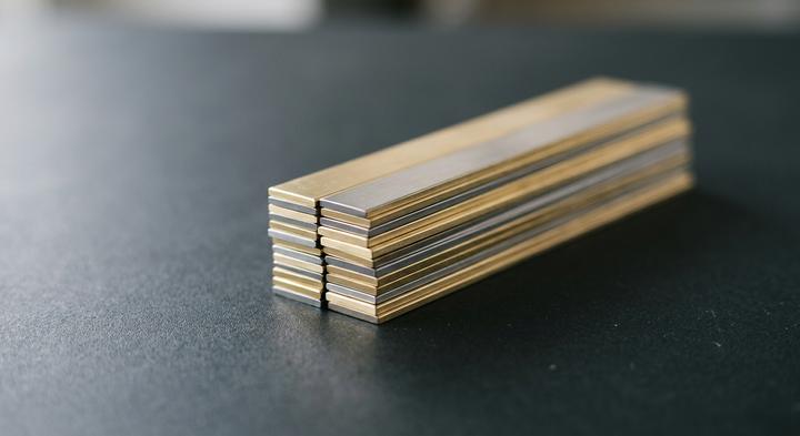
Hardened tool steel is non-negotiable for short-run stamping, even if a tight launch date makes soft prototype alloys look tempting. This is Why Rapid Tooling Timelines backfire: teams that Run Stamping Projects Rushing through the initial tool build to hit a pilot run deadline usually watch their dimensions drift after the first few hundred strokes. When you machine a prototype die from soft P20 or 45# carbon steel, it works fine on the first fifty hits of mild steel. But if your actual part uses high-strength materials like SUS301, SUS304, or spring steel, the high shear resistance of those alloys will strip the micro-features on an unhardened die in less than 1,000 hits. The cutting edges round off, the burr height climbs, and the line stops before you have even cleared the pilot phase.
The real mistake here is treating a prototype tool as a throwaway shortcut rather than a true blueprint for mass production. If the prototype stage does not mirror the physical realities of the final progression strip—including bending angles, nesting, and material springback—the part design is essentially useless for scaling up. This is where Upfront Design reviews protect the budget. Catching a tolerance stack-up or a tight bend radius on a drawing is a five-minute CAD fix; finding it after the tool steel is cut is a disaster. At WenXinDa, we have watched teams lose three weeks of launch runway because they skipped a basic DFM check to save forty-eight hours on the front end.
The math of tooling modifications is unforgiving once the steel goes to heat treatment. A simple two-millimeter change to a bracket hole does not mean a quick drill press adjustment; it means two weeks of wire-EDM time, precision grinding, and stress-relieving heat-treat cycles to avoid cracking the block. Saving a few days on the initial tool design is an incredibly expensive way to generate high-precision scrap. In short-run stamping, the fastest way to get your first thousand parts on spec is always to design the tool as if you need fifty thousand.
The Prototype Tooling Matrix: Balancing Cost, Tolerance, and Tool Lifespan
How do you choose tooling for a metal stamping run under 5,000 parts?
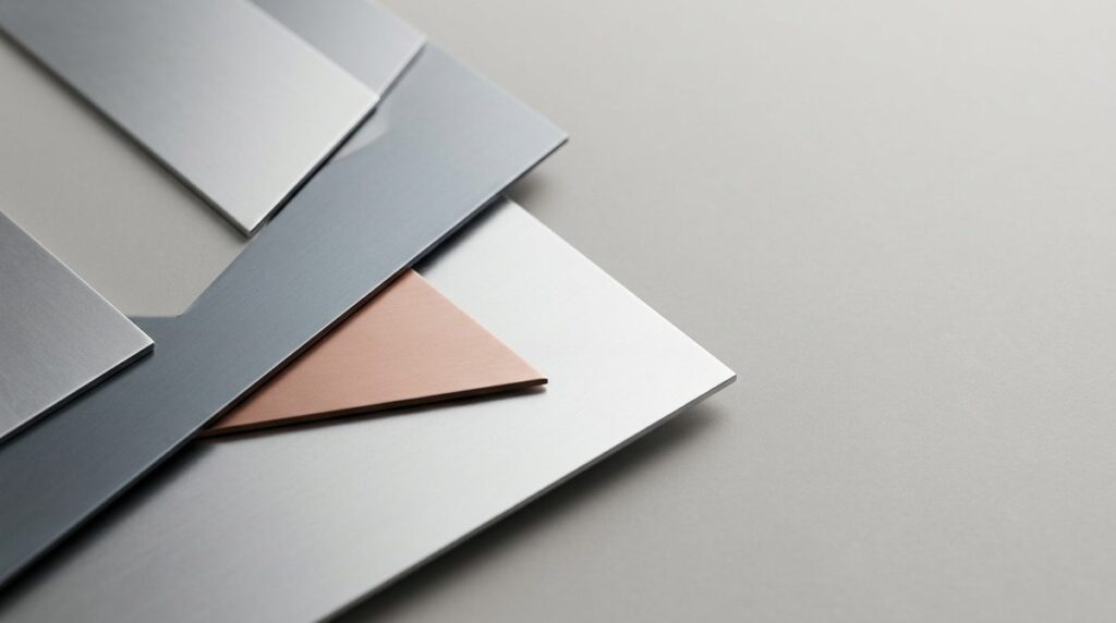
To evaluate expected tool lifespan how you match sheet thickness and tensile strength to die wear limits determines your actual cost per part. Holding a tight ±0.05 mm tolerance on thin electronic contacts requires hardened insert dies made from D2 or Cr12MoV, even on low-volume runs under 500 parts, because softer carbon steels round over and burr almost immediately. Thick, high-strength metals chew through unhardened modular stage tools under high shear stress, destroying the punch before you finish your pilot run.
| Tooling Category | Ideal Run Volume | Achievable Tolerances | Typical Die Steel Grade | Relative Tooling Cost | Primary Geometric Risk |
|---|---|---|---|---|---|
| Modular Stage Tools | 1 to 500 | ±0.15 to ±0.25 mm | Pre-hardened 45# / P20 | Low (1x Baseline) | Edge burrs and flange variation from manual placement |
| Hardened Insert Dies | 500 to 5,000 | ±0.05 to ±0.10 mm | D2 / Cr12MoV (semi-hardened) | Moderate (2.5x to 4x) | Micro-feature wear on high-tensile copper or steel runs |
| Hardened Progressive Tooling | 5,000+ | ±0.02 to ±0.05 mm | DC53 / ASP-23 (fully hardened) | High (8x to 15x) | Pilot pin misalignment during high-speed feed cycles |
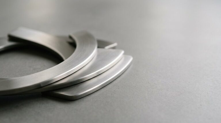
Selecting high-performance alloys and maintaining precise strip alignment is critical to preventing tool wear during short-run stamping.
Finding the Physical Tipping Point
Calculating manual labor accumulation against upfront die construction reveals the physical tipping point. The manual transfer process requires hand-positioning the blank for every bend or pierce, which drives up unit costs and introduces placement errors. For complex geometries with nested folds, progressive tooling holds the workpiece on a continuous carrier strip to guarantee alignment. Engineers at WenXinDa analyze how material thickness and strip layout behave under dynamic tonnage to determine if progressive tooling is more cost-effective than manual stage operations over the full production run. This calculation is especially critical when dealing with materials over 1.5 mm thick, where handling fatigue slows manual cycles and increases the defect rate.
Applying Prototype Strategies: Three Technical Case Pathways
The QC engineer on the 6:00 AM shift stares at a scrap bin of deformed electrical terminals, realizing the latest coil of C5191 phosphor bronze is fighting the bending die with far more springback than the previous batch. In precision metal stamping, raw material temper shifts from coil to coil, meaning a static prototype tool will constantly produce out-of-tolerance parts. To prevent this, toolmakers must avoid monolithic dies and instead implement adjustable bending blocks with shim-controlled inserts. This allows the press operator to dial in micro-adjustments directly on the shop floor without pulling the entire tool to be recut, keeping the critical contact gaps stable.
Scenario A: Adjusting Bending Blocks for Phosphor Bronze Springback
When fabricating springy, thin-gauge C5191 electrical contacts, high-strength alloys store significant elastic energy that releases the moment the punch retracts. To counter this coil-to-coil springback variation, the prototype tooling must utilize modular forming stations with dedicated shim pockets. Instead of rebuilding a solid die block when a new raw material batch arrives, engineers insert or remove ground steel shims behind the forming punch to overbend the material by a fraction of a degree. This mechanical tuning process ensures that variations in yield strength are absorbed during short-run production before committing to high-volume progressive die geometries.
Scenario B: Testing Deep-Draw Limits on SUS304 Sensor Housings
When drawing cylindrical SUS304 stainless steel sensor housings, jumping directly to a progressive die runner is a massive capital risk. A practical mitigation step is to run a single-action hydraulic press test using single-stage prototype draw tooling to locate the material’s physical thinning, wrinkling, and tearing limits. Pushing these prototype cups to failure under varying binder forces allows the toolroom to map the precise draw ratio and blank-holder pressures required. Capturing these physical limits early prevents catastrophic splitting and reduces the number of expensive engineering changes required once the high-speed progressive dies are designed.
Scenario C: Scaling Consumer Casings via Modular Master Frame Systems
Moving a custom consumer casing from a 500-unit trial to a 30,000-unit pilot run often creates a severe tooling capital bottleneck. To avoid sinking the entire budget into a dedicated high-speed progressive die or settling for slow, high-labor stage tools, procurement teams can deploy a modular master frame system with swappable cavity blocks. At WenXinDa, we utilize standardized master shoes that remain in the press while we swap only the custom cavity inserts for the casing run, saving up to 60% in upfront tooling costs. Before signing off on a dedicated tool set for a mid-volume launch, ask your stamping manufacturer if your part envelope can be accommodated in a modular master frame to preserve your capital.
Design Pitfalls That Destroy Prototype Tooling and Blow the Budget
Stamping die failures and blown budgets are decided on the physical press bed, not inside a virtual CAD simulation. CAD software assumes ideal metal conditions, but real press operations introduce heat, variable friction, and extreme tonnage that digital models cannot replicate. When high-value alloys stretch past their mechanical limits, theoretical clearances quickly turn into expensive scrap. Skipping these physical realities during the early tooling stages is the single fastest way to run a short-run project off its financial tracks.
If the 3D model clears digital collision checks, the physical stamped part will not split.
Digital tools treat sheet metal as an isotropic, perfectly uniform sheet. They completely ignore grain direction, localized tensile limits, and the severe thinning that happens at a tight bend radius. When a hardened steel punch actually hits physical stock, the material near those tight corners stretches beyond its elongation limits, splitting the seams wide open. Before any steel is cut, the stamping engineer must calculate the material’s true minimum bend allowance and plan for springback, ensuring the tooling geometry accounts for real-world material flow rather than mathematical perfection.
A prototype stage tool can easily run at production speeds for a short pilot run.
Speed shatters temporary tooling because prototype dies are engineered for slow-stroke, single-hit operation. They lack the robust guide pins, heavy-duty stripper plates, and thermal management of high-speed production systems. Forcing a temporary tool to run under continuous, rapid press strokes introduces high-frequency vibration that cracks dies and breaks carbide punches. If you need several thousand parts, the correct path is using modular master plates with hardened tool steel inserts—which survive rapid strokes without the massive upfront expense of dedicated high-speed tooling.
Nesting and strip layout are manufacturing details that can wait until the design is frozen.
Postponing the strip layout forces nesting compromises that easily push scrap rates past 40%, inflating the invoice for expensive materials like beryllium copper. If the carrier ribbon is designed too narrow or the progression pitch is too cramped to save material, the strip will buckle, jam the coil feeder, and smash the active areas of the die. Co-designing the nesting layout alongside the part geometry is the only way to safeguard your raw material budget before the die pocket dimensions are permanently cut into the tool steel.
Are you willing to sign off on a tooling invoice before your supplier shows you a physical strip layout and a documented progression plan?
The Toolroom Audit: Hard Verifications to Make Before Cutting Steel
How do you verify if a metal stamping supplier has in-house toolroom capacity?
Evaluating an equipment list on a PDF flyer is never enough. To protect your timeline, you must confirm the vendor actually operates high-precision machining assets under their own roof, because when a stamping shop outsources their wire-EDM or profile grinding, a minor mid-run modification instantly adds five to seven business days of logistical lag while the die travels back and forth.
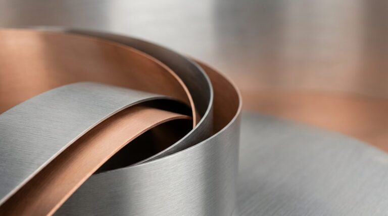
Verifying physical prototype dimensions against dynamic press forces prevents costly rework before final progressive die hardening.
Production Tooling Verification Checklist
| Tooling Capability Check | Required Technical Standard | Red Flag / Substandard Shortcut | Significance to Short-Run Delivery |
|---|---|---|---|
| House Machining Assets | Low-speed wire-EDM holding tolerances down to 0.005 mm; wet surface grinders for tool maintenance under one roof. | Outsourcing wire-EDM work to external shops; relying on manual grinders for critical die modifications. | Compresses emergency tool modifications from a week down to under 24 hours, securing your critical Run Delivery. |
| Strip Layout Approval | Physical strip layouts detailing progression pitch, carrier margins, and station-by-step deformation. | Approving the tool build solely based on a 3D CAD model without a step-by-step strip layout simulation. | Prevents progressive strip binding and catastrophic die crashes that force complete tool rebuilds. |
| Article Match | CMM and optical scanning reports mapped directly back to physical press samples under high-tonnage conditions. | Using hand-calipers on isolated loose parts without a continuous-strip inspection report. | Ensures that tool-side springback compensation is mathematically verified before volume run. |
| Tool Steel Specification | D2 or DC53 tool steel certificates with heat-treatment reports verifying 58–62 HRC hardness. | Using generic local ‘cold work steel’ without heat-treat trace logs or verified hardness. | Prevents premature edge chipping, eliminating mid-run repolishing downtime. |
At WenXinDa, we manage this transition from engineering drawing to physical steel by keeping our wire-EDM, CNC milling, and surface grinding under our own roof. This setup means that when a trial reveals a springback issue or carrier strip misalignment, we recut the inserts on our own machines instead of waiting for a third-party tool shop to slot us into their schedule. The difference shows up when you run the first thousand parts: instead of a month-long back-and-forth over dimensional discrepancies, you get a verified process where the physical tool and the digital design match up exactly.
Securing First-Time Tooling Approvals: Technical Boundaries and Next Steps
Now that the decision criteria and material pathways for alloys like C5191 phosphor bronze and SUS304 stainless steel sit in a clear technical framework, the final milestone before cutting tool steel is aligning on the physical press constraints. Most critical delays in custom metal stamping do not arise from CNC machining errors but from unaddressed design-to-tooling friction that only shows up under dynamic press forces. Implementing a rigorous, engineer-to-engineer strip layout review before hardening the tool steel typically catches up to 90% of structural issues—such as pitch progression misalignments, carrier strip deformation, incorrect pilot pin placement, or thin-wall stress concentrations—while the tool is still soft and easily modified. This joint engineering review bridges the gap between theoretical CAD models and the high-speed reality of the mechanical press, verifying how the metal flows through each progressive stage and resolving potential springback or tearing risks long before the die is mounted to the bolster plate.