EMI Shielding Solutions: Precision Metal Stamping for Compact Electronics
Choosing EMI Shielding Cans: Why the Standard Sample Sheet Fails in the SMT Line

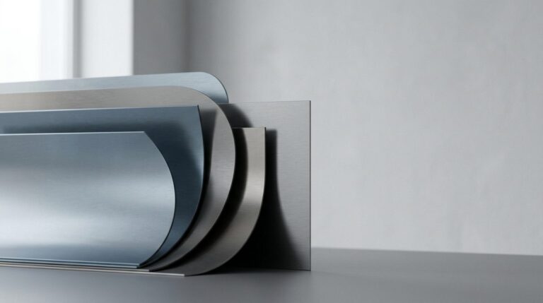
Visualizing precision control: scanning systems check for micro-level coplanarity and surface flatness.
A high-speed pick-and-place nozzle stops dead on the SMT line, throwing a repeated vacuum pressure error because a newly loaded pocket of metal shields has warped by a fraction of a millimeter. In the quiet environment of an R&D lab, hand-soldered prototype shields worked perfectly, but under the relentless speed of automated assembly, a coplanarity deviation of over 0.08mm is enough to make vacuum nozzles reject parts or misalign them on the solder paste. When procurement managers source custom Shielding Cans, this is exactly where the Standard Sample Sheet Fails to protect a production schedule; a single-cavity soft-tooled sample tells you if the shield fits the board, but it says absolutely nothing about how the metal will behave when fed from a high-speed reel.
Transitioning from slow, hand-soldered prototypes to high-speed, multi-cavity progressive metal stamping introduces dynamic physical forces—like material stress and springback—that do not exist in low-volume sample runs. If the stamping layout does not account for these forces from the start, the ultra-thin 0.15mm foil will warp during progressive deformation, turning a low-cost commodity part into an expensive line-down bottleneck. Procurement teams frequently make the mistake of approving components based solely on unit price, ignoring the fact that a 2% SMT scrap rate completely erases any upfront tooling savings.
As a precision metal stamping specialist, WenXinDa aligns commercial targets with manufacturing reality by designing production-ready features directly into the initial tool layout. By engineering precise pick-and-place targets, optimized corner radii, and custom reel-wound carrier strips during the early design phase, we ensure that bulk-stamped parts maintain their structural flatness throughout packaging, shipping, and automated feeding. True cost efficiency in EMI shielding is not measured by the lowest piece price on a sample sheet, but by how cleanly the parts release from the tape on the SMT line.
Design Axes of Shielding Cans: Specifying Foil and Metal Stamping Tolerances
What parameters must a hardware team lock down on an RFQ before sourcing Shielding Cans with specific metal stamping tolerances?
When dropping from standard 0.20mm tinplate down to ultra-thin foils of 0.08mm to 0.12mm, progressive metal stamping physics undergoes a complete regime shift. Instead of relying on gravity or basic friction feeds, handling these thin webs without stretching the metal requires active loop tension control on the progressive dies to protect the flatness of the part. Specifying Foil at these limits forces a hard engineering trade-off: you are balancing the absolute Z-height constraints of Dense Wearables against the structural stability of the shield on the SMT line. Understanding these mechanical Design Axes of Shielding Cans is the first step in balancing component cost against automated assembly yield.
| Buyer Profile | Design Format | Material Thickness | Coplanarity Limit | Tooling Investment Tier | Solderability vs Rework Ease |
|---|---|---|---|---|---|
| Dense Wearables (Smartwatches, TWS) | Single-piece Foil | 0.08mm – 0.12mm | ≤ 0.08mm | Low | Excellent solderability; zero rework ease (requires desoldering shield) |
| Consumer Electronics (IoT, Smart Home) | Single-piece Standard | 0.15mm – 0.20mm | ≤ 0.10mm | Medium | Cost-effective; edge oxidation risk on sheared SPTE; zero rework |
| Industrial & RF Modules | Two-piece Frame & Lid | 0.20mm – 0.30mm | ≤ 0.12mm | High | Frame soldered permanently; lid snaps off for clean component rework |
Balancing Tooling
The trade-off between single-piece and two-piece configurations often boils down to upfront costs versus long-term line yield. While single-piece cans offer the lowest unit price, they must be desoldered if a component fails post-reflow, risking board delamination. A two-piece frame-and-lid design avoids this, though it carries a higher tooling fee and eats up more PCB footprint. The Primary Risk here is material choice: while standard tinplate is cheap, its sheared edges oxidize in humid storage, whereas C7521 Nickel Silver maintains native oxidation resistance on cut edges and preserves clean solderability. When designing these systems, the golden rule is to never specify a coplanarity tolerance tighter than your stamping partner can verify on a mechanical shadowgraph—otherwise, you are paying for precision that your supplier cannot reliably measure during a production run.
Scenario Alignment: SMT Progressive Metal Stamping vs. Manual Clip-On Shields
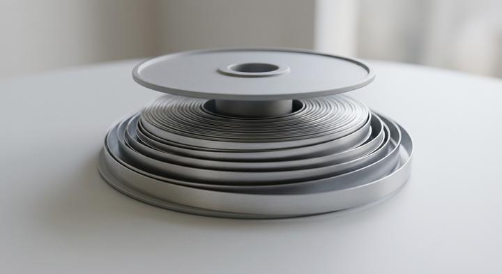
Optimized packaging: automated systems require clean, continuous feed carriers to maintain high-speed line efficiency.
An SMT line manager staring at a rising stack of pick-and-place vacuum nozzle errors at 2:00 AM knows exactly when a theoretical design choice has failed on the production floor. Translating precise tolerance parameters from a technical drawing to a running assembly line requires aligning the metal stamping method with the specific spatial layout, clearance constraints, and total production volume of the project. When a design calls for shielding, the decision between high-speed progressive metal stamping and manual multi-piece assemblies is rarely about unit cost alone; it is a direct trade-off between line efficiency, physical clearance, and upstream tooling capital.
Scenario A: High-Density Consumer Wearables (Ultra-Thin Foil Focus)
High-volume consumer wearable boards pack components into fractions of a millimeter of vertical space, creating a severe, unyielding Z-height barrier. For these tight envelopes, sourcing 0.08mm to 0.12mm ultra-thin shielding cans packaged on tape-and-reel for automated SMT lines is the only viable path. Single-piece shielding foils are stamped using high-speed progressive dies directly into specialized carrier strips, allowing the pick-and-place machine to treat the shield like any other passive chip component. Because there is zero headroom to accommodate a separate clip-on frame, the shield is reflow-soldered directly to the board. This eliminates manual handling costs but trades away post-assembly rework ease for an ultra-thin physical profile. To prevent the delicate metal stretching that routinely warps these micro-foils during high-speed stamping, WenXinDa utilizes active loop tension controls on the stamping press, ensuring that each pocket releases cleanly at the nozzle without jamming the tape feeder.
Scenario B: Rugged Industrial & RF Modules (Removable Lid Focus)
In an industrial IoT gateway run, a hardware team was prepping for a smart-grid deployment when the RF engineering group realized the wireless transceivers required manual component tuning and frequency calibration after final board assembly. This forced an immediate choice between a low-cost, single-piece shield—which would require delicate manual desoldering for every test pass—or a two-piece progressive-die stamped frame with a removable clip-on cover. Opting for a two-piece SPTE (tin-plated steel) frame with a manual clip-on shield allowed the team to adjust components and flash firmware without exposing neighboring components to repeated thermal stress. While the two-piece assembly requires manual lid installation, it bypasses the need for desoldering stations on the rework line, protecting fragile RF paths and saving hundreds of manual operator hours during the initial field pilot phase.
Technical Blind Spots: Why Cheap Metal Stamping Dies Inflate Assembly Rejection Rates

Sharp edges and tight clearances: high-quality tooling eliminates micro-burrs and preserves component geometry.
A cheap metal stamping die acts as a long-term tax on SMT line yield. Sourcing shortcuts represent the Technical Blind Spots that buyers miss, directly explaining Why Cheap Metal Stamping dies fail. Skimping on tooling development ensures worn punch edges and shifting clearances will warp your shielding cans, and these poor quality Dies Inflate Assembly Rejection Rates Downstream. Saving a few thousand dollars upfront on soft tooling guarantees you spend ten times that amount troubleshooting component alignment, solder shorts, and crushed shielding walls on the line.
Stamping pre-plated tinplate (SPTE) shears both the base metal and its soft tin plating. Budget tooling dulls rapidly, dragging the tin rather than cleanly shearing it, which leaves razor-sharp micro-burrs along the cut edge. Under the pressure of SMT placement nozzles, these shards puncture the PCB’s solder mask, bridging copper traces and causing short circuits that escape early inspection. To avoid this, specify a burr limit under 10% of the material thickness. At WenXinDa, we prevent these punctures by using in-house tool steel hardening to maintain sharp shear edges, backed by inline sensor testing to monitor punch displacement in real time.
A golden sample only shows what a pristine die does on its first few strokes, not on stroke fifty thousand. Cheap progressive dies lack carbide inserts, meaning punches slip out of alignment under high-speed press vibration. This causes progressive tolerance drift, warping your shielding cans after a few days of manufacturing. At WenXinDa, we counter this drift by running inline optical CCD dimensional screening at the press to measure critical clearances on every stroke. If a supplier cannot show how they track progressive alignment wear, expect your assembly yields to drop after the first batch.
Standard bulk-packaging is a safe, cost-effective way to ship lightweight metal shielding cans.
Factory Audits: Vetting a Metal Stamping Supplier for High-Volume Shielding Runs
The choice between stamping progressive dies and snapping on manual clips isn’t just a spreadsheet exercise on tooling amortization; it is a commitment to a physical process. Moving from those CAD dimensions to the floor requires running Factory Audits to vet your Metal Stamping Supplier, specifically when planning high-Volume Shielding Runs While keeping real-world press physics in mind.
| Audit Verification Area | Required Technical Evidence | The Operational Red Flag | House Audit Owner |
|---|---|---|---|
| House Toolroom Control | In-house wire EDM logs, CNC grinding machine schedules, tool maintenance intervals mapped by stroke counts, and a dedicated spare-die inventory (punches, die inserts, lifter pins). | The supplier outsources major tool modification or punch sharpening to external shops, adding days of downtime and erratic tolerance drift when a progressive die wears down mid-run. | Tooling Engineer / Toolroom Supervisor |
| Inline QA Controls | Live demonstration of automated acoustic sensors or high-resolution CCD vision systems integrated into the press; digital logs of automated press-stops triggered by strip misfeeds. | Relying entirely on manual, post-stamping inspections at the collection bin, which can let thousands of out-of-spec parts stack up before anyone notices the drift. | Quality Assurance Manager / Lead Line Inspector |
| Material Traceability | Original Mill Test Certificates (MTC) matched to coil heat numbers; incoming thickness tolerance charts verifying raw variations stay within ±0.005mm. | Thin-gauge tinplate or copper-nickel coils stored with hand-written, generic labels, or running commercial-grade alloys without incoming verification protocols. | Incoming Quality Control Team |
When we walk a factory floor, we bypass the polished reception area and go straight to the tooling crib. For a 0.10mm shield run at 200 strokes a minute, an ISO 9001 certificate on the office wall matters far less than whether the toolmaker has a spare punch ready when the active one chips. Progressive dies suffer relentless micro-wear; if the supplier has to truck the tool across town for sharpening, your line is down for the weekend. At WenXinDa, we keep the toolroom ten steps from the presses—because the cost of a shield is won or lost in how fast you can pull, sharpen, and re-key the die.
Securing the RF Signal: Precision Metal Stamping Delivery with WenXinDa
Now that the mechanical trade-offs between manual clip-on shields and tape-and-reel progressive stamping sit in a comparative framework, the real bottleneck becomes execution under actual high-volume production pressure. This is where Precision Metal Stamping Delivery must match physical limits. For WenXinDa, this means operating strictly within a specialized thin-gauge stamping envelope: producing custom-designed shielding cans from materials like Nickel Silver, SPTE, SUS430, and Beryllium Copper at thicknesses ranging from 0.08mm to 0.30mm.
Mitigating high-volume assembly risk requires freezing the design before tooling steel is cut. When we conduct a design review, we evaluate carrier strip pitch issues, stress-relief cutouts, and corner radius dynamics on paper. Fixing a progressive die after the tooling is heat-treated is expensive and easily ruins schedules. Running these reviews upfront is how we guarantee a progressive die life of up to 1 million strokes, backed by automated inline optical inspection arrays that monitor flat surfaces during the run to prevent coplanarity spikes on the SMT line.
If you are still tuning your RF layout and want to avoid early tooling investments, we bypass hard tooling entirely with an 8 day prototype chemical etching service. This lets your engineering team run benchtop RF shielding tests and trace routing validations before committing to physical progressive dies. Once the layout is frozen, we transition the design straight into high-speed stamping. To begin, upload your 3D CAD STEP file directly to our portal. Our engineering team will review the geometry and send back a design-for-manufacturing (DFM) analysis and a coplanarity feasibility report within 24 hours.