Scaling Consumer Electronics Production via CNC Machining
Why the Prototype-to-Production Gap Breaks So Many Electronics Launches
Transitioning from prototype to production requires a shift from manual precision to repeatable process efficiency.
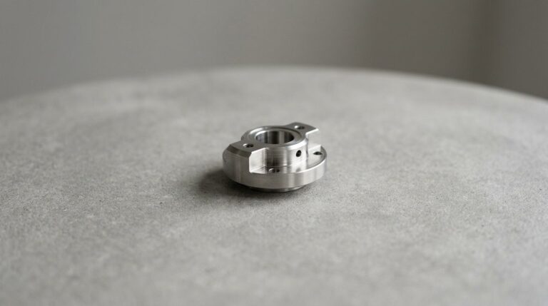
Most electronics projects don’t fail because the design was bad; they fail because the prototype was too good. When you hold a CNC-machined sample, you’re holding a part made with infinite time and manual intervention. That 10-unit pilot is a lie. It hides the reality of material shrinkage, tool wear, and the cooling rates that define a 500-unit run. If you don’t account for these variables before you lock the design, the production floor will force you to choose between massive scrap rates or a product that doesn’t fit together.
At WenXinDa, we see the same mistake every week: buyers treat the prototype as a final product rather than a process test. A prototype is a shape; production is a repeatable sequence. If your design relies on hand-finishing or specific CNC settings that can’t be replicated at speed, you aren’t ready for a 1,000-unit order. We emphasize design-for-manufacturability (DFM) early because it’s cheaper to adjust a tolerance in CAD than it is to fix a mold after the first batch of production has already hit the floor.
Don’t treat your first sample like a showcase. Treat it like a stress test for your supply chain. If you can’t replicate the fit and finish of your 10-unit pilot on the 500th unit, the process is the problem, not the machine. Before you sign off on the tooling, ask your supplier to show you the tolerance stack-up for the full run, not just the golden sample. The best way to avoid a rework cycle is to assume the first production run will be the hardest, and build your tolerances to survive it.
CNC Machining Specs: What Actually Drives Your Unit Cost
How do you actually strip the excess cost out of a CNC quote without compromising the build? Most buyers get hung up on the raw material price, but that’s rarely where the money goes. The real cost is buried in how long the spindle runs, how often the tools break, and how much manual labor is needed to clean up the parts before they hit the assembly line.
| Decision Factor | Cost Driver | Risk | Recommendation |
|---|---|---|---|
| Material | 6061 vs 7075 Aluminum | Tool wear on 7075 | Use 6061-T6 for standard enclosures |
| Tolerances | Machining time | Scrap rate at <±0.05mm | Target ±0.05mm for assembly |
| Finishing | Labor/Process steps | Inconsistent anodizing | Bead blast + clear anodize |
| Volume | Setup/Tooling amort. | High cost at <50 units | Batch to 500+ for efficiency |
If you are spec-ing 7075 aluminum for a standard enclosure, you are paying for rigidity you likely don’t need. It eats through end mills faster than 6061-T6, and your supplier will pass that tool-wear cost directly to you. Stick to 6061-T6 unless the part is structural. Similarly, don’t chase tolerances tighter than ±0.05mm unless the assembly demands it. That threshold is the line between a standard run and a high-scrap, high-cost nightmare. If you can hold ±0.05mm, you get a reliable fit without the secondary precision operations that kill margins.
Finishing is where most quotes get messy. Bead blasting followed by anodizing is the industry standard because it hides the minor tool marks that are inevitable in high-speed machining. If you start adding custom textures or multi-step coatings, you are looking at a 20% jump in unit cost. When you move from 50 units to 5,000 units, the setup time for these finishes becomes a fixed cost that gets diluted, but only if the design is locked. If you change the geometry mid-stream, you trigger re-qualification costs that wipe out any volume-based savings. Lock the finish specs before the first 500 units hit the line.
Three Real-World Scenarios: From Proof-of-Concept to Market Launch
The Proof-of-Concept Trap
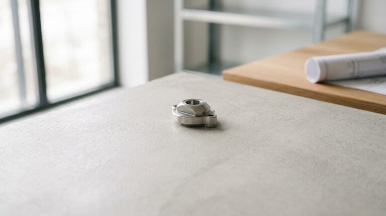
Most designers fall for the ‘golden sample’—a part machined with infinite time and manual intervention that simply won’t hold up on a production line. When a studio brings a prototype to a manufacturer, the first friction point is usually geometry that requires five separate setups. If you prioritize aesthetic perfection over assembly-ready tolerances, you are paying for the machine’s idle time during constant tool changes. Before the first chip is cut, check your internal radii against the shop’s standard tooling. If you can’t machine it in three axes, you aren’t designing for production; you’re designing for a display case.
The Pilot Run Reality
For a 500-unit pilot, the failure rarely happens at the CNC stage; it happens at the assembly bench. A common oversight is failing to account for material shrinkage or the added thickness of surface finishes like anodizing, which can turn a perfect snap-fit into a jammed component. At WenXinDa, we see this most often when buyers skip the ‘fit-check’ phase. If you don’t test the assembly fit before committing to a full-scale anodizing run, you risk a week of manual filing on the factory floor. Never approve the final finish until you have verified the fit with the actual coating applied.
The Full-Scale Transition
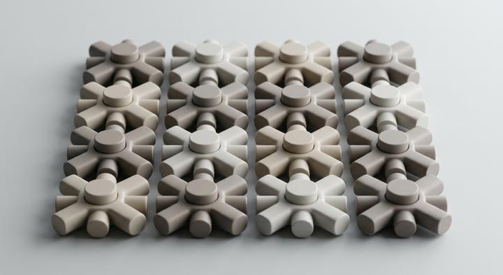
Moving to 5,000+ units changes the math from ‘how do we make this’ to ‘how do we make this fast.’ The bottleneck here is almost always fixturing. If your part design doesn’t allow for batch-loading on a pallet, your unit cost will stay flat regardless of volume. We often see startups struggle because they didn’t include a simple, standard mounting hole that would allow the shop to load ten parts at once. Redesigning for the fixture can cut cycle times by 25% or more. If you aren’t designing for the pallet, you are still designing for a prototype, not a production line.
If you can’t replicate the fit and finish of your pilot on the 5,000th unit, the process is the problem, not the machine.
Three Common Mistakes That Derail CNC Electronics Projects
Most CNC electronics projects stall not because of design flaws, but because the procurement process treats production like a scaled-up prototype. If you are managing a launch, the difference between a successful batch and a scrap pile usually comes down to how you handle tolerances, wall thickness, and finish standards before the first PO is signed.
If the sample passes, production will too.
A sample is a static object; production is a dynamic process. A prototype is often hand-finished or run on a machine with infinite setup time, masking the reality of tool wear and thermal drift that occurs over a 500-unit run. If you cannot replicate the fit and finish of your pilot on the 500th unit, the process is the problem, not the machine. Ask your supplier for a staged inspection plan that defines what gets checked at the 10%, 50%, and 100% marks of the run, rather than relying on the ‘golden sample’ to represent the entire batch.
Over-specifying tolerances is the safest way to ensure quality.
Demanding ±0.01mm when ±0.05mm suffices is a direct path to a 30% price hike. Tight tolerances force slower feed rates, frequent tool changes, and secondary operations that add no functional value to an electronics enclosure. If you are unsure, ask the machine shop where the ‘natural’ tolerance of their setup lies for your specific geometry. Aligning your design with their standard process is the most effective way to lower costs without sacrificing the integrity of the build.
Thin-walled enclosures are just as stable as solid blocks.
Thin walls warp during high-speed machining because the internal stresses of the material are released as the metal is removed. If your design requires thin walls for weight reduction, you must account for specialized work-holding or multi-pass machining to maintain stability. At WenXinDa, we often flag these geometries during the DFM phase because a part that looks perfect in CAD often distorts the moment it leaves the fixture. Is your current supplier prepared to provide a DFM report on your wall thickness before they cut the first piece of metal?
How to Vet a CNC Supplier for Consumer Electronics
How do you verify a supplier can actually handle your production volume without needing constant oversight? Most buyers get distracted by polished factory photos, but the real story is in the QC logs. A shop that hits a 0.05mm tolerance on a single prototype is common; a shop that holds that same tolerance on the 500th unit of a 5,000-unit run is rare. You aren’t just buying machine time; you are buying the supplier’s ability to manage the drift that happens once the coolant heats up and the tools begin to dull.
| Ask | Expected Evidence | Red Flag | Responsible Party |
|---|---|---|---|
| Average yield rate | Data from last 12 batches | “We don’t track that” | Quality Manager |
| DFM review process | Formal report on design risks | No feedback provided | Engineering Team |
| Past similar projects | Samples or photos of geometry | Refusal to share examples | Account Manager |
| Material traceability | Mill test certificates (MTC) | Generic material claims | Procurement |
When you ask for the average yield on the last 12 batches, you are testing the supplier’s honesty. Anyone can show you a ‘golden sample’ that was hand-finished for three hours, but the yield rate tells you how many parts actually passed QC on the first pass. If a supplier claims a 100% success rate, they are either hiding the scrap rate or charging you for it. A transparent partner will show you the 3% defect rate they manage and explain exactly how they catch those parts before they reach your assembly line.
Design for Manufacturing (DFM) is where the gap between a job shop and a production partner becomes clear. A true partner will push back on your design if they see a feature that will cause tool chatter or excessive cycle time. If you send a file and get a quote back in ten minutes without a single question, you are paying for their silence. We find that a 15-minute DFM review before the first cut saves weeks of rework later. If you need to align your tolerances with production realities, request a DFM review or download our latest technical spec sheet.
Moving Forward with Your CNC Machining Project
Now that you have a clear view of the trade-offs between prototype precision and production-scale reality, the final step is ensuring your design doesn’t hit a wall when it reaches the factory floor. The transition from a successful pilot to a 5,000-unit run is rarely about the machine’s capability; it is about whether the design was built to survive the realities of tool wear, material shrinkage, and the inevitable pressure of a production schedule. At WenXinDa, we have seen enough projects stall at the final hurdle to know that the most effective way to protect your margins is to lock your DFM requirements before the first tool is ever cut. We focus on balancing the high-end tolerances your product demands with the cycle-time efficiency that keeps your unit costs from spiraling.
If you are ready to move from a design concept to a reliable production run, the most efficient way to start is by aligning your CAD files with our manufacturing standards. You can download our DFM checklist to identify the common geometry traps—like unnecessary deep-pocketing or aggressive internal radii—that inflate your spindle time and drive up costs. Once your files are ready, contact our engineering team to book a 20-minute DFM review; we will look at your current design and provide a clear assessment of what needs to be adjusted to ensure your production run hits your target volume and quality specs without the need for expensive mid-stream retooling.